


I don't understand these diagrams which show the turbo and Red/Yellow/Blue lines coming from them. I understand the Blue goes to fresh air intake. I just did a total restoration basically, based off of everything that I have learned here on MVS as well as iPd and volvopartswebstore. I knew nothing about cars going in to this, couldn't even tell you where a spark plug was. I tried my best to keep track of everything I removed, and mark what I could. Here is a list of what I cleaned, replaced etc.
Spark Plugs, Motor Oil/Filter, Upper Engine Torque Mount, Fuel Filter, Transmission Filter/Gasket, Vacuum Hoses, PCV System, Intake Manifold Gasket, ETM clean/gasket replace..etc.
Basically, I got everything back together within a month (pretty good for knowing nothing about cars). But I have this one stinking part that I am confused about. I will post pictures below. But I have a hose tree thing with two directional valves (I'm assuming air). I have no idea where the following hoses need to go from these nipples: Top middle intake manifold, bottom right nipple intake manifold (not large but small below. TCV line routing, nipple coming up off of the plastic charge air pipe). Anything will help. watch below for pictures.
2000 S80 T6 Directional Valve/TCV Questions
This topic is in the MVS Volvo Repair Database »
Turbo S80 TCV & Vacuum Line Routing
-
Godfrey de SaintOmer
- Posts: 5
- Joined: 14 April 2014
- Year and Model: 2000 Volvo S80 T6
- Location: Iowa, USA
- Been thanked: 1 time
-
Godfrey de SaintOmer
- Posts: 5
- Joined: 14 April 2014
- Year and Model: 2000 Volvo S80 T6
- Location: Iowa, USA
- Been thanked: 1 time
heres the pictures..
- Attachments
-
-
-
-
-
-
-
-
-
-
Godfrey de SaintOmer
- Posts: 5
- Joined: 14 April 2014
- Year and Model: 2000 Volvo S80 T6
- Location: Iowa, USA
- Been thanked: 1 time
Is there anybody who can help with this issue? I believe the directional valves are 5mm in, 9.5mm out? And the 2nd picture there is possibly the purge valve? I honestly don't know, but it is attached to the rad fan, drivers side. Also, from reading the diagrams, I don't know which turbo deal is which, (compression, waste gate). I am assuming for now that the thin metal pipe on the back of the motor, drivers side, is the turbo waste gate? Pleeeeasee somebody help! I really need my car back. Thank you.
-
matt5112
- Posts: 101
- Joined: 30 May 2013
- Year and Model: 1999 S65
- Location: spain
- Been thanked: 3 times
So starting with the TCV:
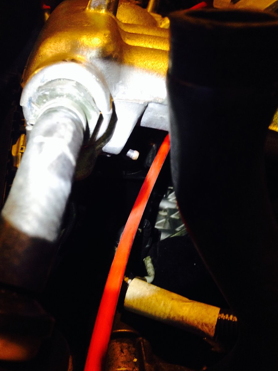
Yellow/wastegate goes to the metal tube that's by itself near the trans dipstick. No check valves there. This one here:

Blue/fresh air goes on the bottom of the tube right after the MAF on the fitting closest to the engine. There should be two more fittings there. Large one for the diverter valve/compressor bypass valve dumped air flow. Medium sized for the evap.
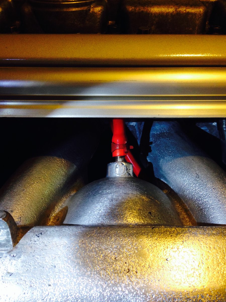
The Red/turbo pressure line goes to the two tubes that merge into one on the top centre of the engine.
The pressure from the outlet of the turbo presses on the wastegate diaphragm to keep it closed. When the ECU decides there is enough boost, it stops allowing the air from the turbo outlet from going to the wastegate actuator and allows it to go to the compressor inlet tube. The system is a pulse width modulated system meaning it is never "always on", but instead cycled on for longer periods of time to increase boost, and shorter to decrease boost. When the TCV is off, air from the compressor is dumped to the compressor inlet, and the spring pressure in the wastegate is what regulates compressor outlet pressure.
The nipple in this shot:
Goes to this nipple:
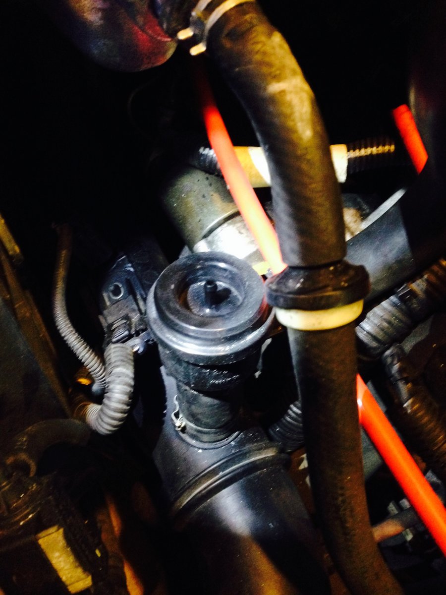
This connects the manifold vacuum/pressure to the compressor bypass valve/diverter valve. This means when the engine is in boost, it holds the valve shut, keeping air flowing to the engine. When the engine manifold is in vacuum just after the throttle blade shuts, the vacuum pulls on the diaphragm in the CBV to allow the pressurized air to return to the inlet side of the turbo. This prevents turbo surge.
I'd have to check my car for the rest. I'd venture to guess one of those check valves is for the evap that also uses a T going into the medium sized nipple on the plastic tube just after the MAF.
I went and checked, the T and two check valves are indeed for the evap.
From the evap vent solenoid, it goes into the T. Going upwards towards the fresh air tube just after the maf, there is a short bit of hose, then a check valve with the arrow pointing towards the fresh air tube, away from the T.
Going towards the engine, away from the evap valve, there is a the other check valve. The arrow points towards the engine. The other end of the check valve goes to this nipple:
Enjoy.
As for a functional overview, the check valves ensure the evap system flows in the right direction only. The purpose is to burn off the gas fumes from the fuel tank. The suction of the engine in vacuum, pulls the fumes when the evap vent solenoid is opened. The check valves prevent air from being pulled from the evap system when the engine does not want it to.
Yellow/wastegate goes to the metal tube that's by itself near the trans dipstick. No check valves there. This one here:
Blue/fresh air goes on the bottom of the tube right after the MAF on the fitting closest to the engine. There should be two more fittings there. Large one for the diverter valve/compressor bypass valve dumped air flow. Medium sized for the evap.
The Red/turbo pressure line goes to the two tubes that merge into one on the top centre of the engine.
The pressure from the outlet of the turbo presses on the wastegate diaphragm to keep it closed. When the ECU decides there is enough boost, it stops allowing the air from the turbo outlet from going to the wastegate actuator and allows it to go to the compressor inlet tube. The system is a pulse width modulated system meaning it is never "always on", but instead cycled on for longer periods of time to increase boost, and shorter to decrease boost. When the TCV is off, air from the compressor is dumped to the compressor inlet, and the spring pressure in the wastegate is what regulates compressor outlet pressure.
The nipple in this shot:
Goes to this nipple:
This connects the manifold vacuum/pressure to the compressor bypass valve/diverter valve. This means when the engine is in boost, it holds the valve shut, keeping air flowing to the engine. When the engine manifold is in vacuum just after the throttle blade shuts, the vacuum pulls on the diaphragm in the CBV to allow the pressurized air to return to the inlet side of the turbo. This prevents turbo surge.
I'd have to check my car for the rest. I'd venture to guess one of those check valves is for the evap that also uses a T going into the medium sized nipple on the plastic tube just after the MAF.
I went and checked, the T and two check valves are indeed for the evap.
From the evap vent solenoid, it goes into the T. Going upwards towards the fresh air tube just after the maf, there is a short bit of hose, then a check valve with the arrow pointing towards the fresh air tube, away from the T.
Going towards the engine, away from the evap valve, there is a the other check valve. The arrow points towards the engine. The other end of the check valve goes to this nipple:
Enjoy.
As for a functional overview, the check valves ensure the evap system flows in the right direction only. The purpose is to burn off the gas fumes from the fuel tank. The suction of the engine in vacuum, pulls the fumes when the evap vent solenoid is opened. The check valves prevent air from being pulled from the evap system when the engine does not want it to.
-
Godfrey de SaintOmer
- Posts: 5
- Joined: 14 April 2014
- Year and Model: 2000 Volvo S80 T6
- Location: Iowa, USA
- Been thanked: 1 time
Thanks a ton! For real thank you matt5112
-
- Similar Topics
- Replies
- Views
- Last post
-
- 3 Replies
- 869 Views
-
Last post by Ludermilch
-
- 1 Replies
- 749 Views
-
Last post by rspi