


I have had this project car for several years and I'm getting back at it to get it running. 2001 V70. I have a crank no start issue with the car. I have spent several weeks reading Vida documentation and wire diagrams with this car. I can jump the Fuel Pump relay and the car starts and runs. The relay itself tests good as I can activate it with 12 volts.
The Vida Design Documentation about the CEM and the Fuel pump indicates there are two other Modules that controls the fuel pump. The ECM and the SRS. The ECM sends a "frequency" signal via the CEM to the Fuel Pump relay via CAN although there is a direct wire in the case of CAN comm failure. The SRS sends signal to the CEM the air bag is OK. I have just replaced the CEM with one from Xemodex which does not fix the said on going no start issue.
So trouble shooting...Referring to the CEM Signal Specification documentation in Vida, the following is what i have found.
CEM pin #E1 ground 0 ohms resistance. I believe the ground to the CEM is good.
CEM pin #B14 ECM Fuel Pump Freqency signal - KeyOff 4.9 Volts / KeyON 12.72 volts. I don't know how to test CAN side of this however, Vida is reading that there is no frequency signal. Not sure what that means or if Vida is reading CAN messages but the voltage seems to be in-line with the documentation.
CEM pin #C14 Signal Fuel Pump Relay - Keyoff 3 Volts / KeyOn 7.2 volts (s/b Ubat or 12.72).
CEM pin #D5 Air bag deployed (OK) - KeyOff 0 volts / KeyOn 0 volts.
Pin #C14 seems to be highly suspect. The ground pin for the CEM is good since it is 0 ohms resistance therefore, I don't believe there is a ground issue dragging down the voltage. The CEM signal documentation indicates #C14 KeyOn should be Ubat or my 12.72 battery volts. Looking at the CEM wiring diagram this voltage for #C14 is coming directly from the CEM. So, does this indicate a bad CEM?
I'm wondering if this CEM from Xemodex is bad although I believe they have a good reputation about testing these before shipping them back.
Diagnosing Crank No Start
-
morganbryane
- Posts: 10
- Joined: 13 September 2015
- Year and Model: V70 2001
- Location: North Carolina
-
RickHaleParker

- Posts: 7129
- Joined: 25 May 2015
- Year and Model: See Signature below.
- Location: Kansas
- Has thanked: 8 times
- Been thanked: 958 times
Try cleaning the edge connector of the CEM and resetting it.
Often that corrects CAN (Controller Area Network) communication defects. CAN is a multiplex serial communication message-based protocol. Anything that degrades the signal can cause problems. On a 17 year old car, tarnished connections is high on the list of suspects.
Often that corrects CAN (Controller Area Network) communication defects. CAN is a multiplex serial communication message-based protocol. Anything that degrades the signal can cause problems. On a 17 year old car, tarnished connections is high on the list of suspects.
⸙⸙⸙⸙⸙⸙⸙⸙⸙⸙⸙⸙⸙⸙⸙⸙⸙⸙⸙⸙⸙⸙⸙⸙⸙⸙⸙⸙⸙⸙⸙⸙⸙⸙⸙⸙⸙⸙⸙⸙⸙⸙⸙⸙⸙⸙⸙⸙⸙⸙⸙⸙⸙⸙⸙⸙⸙⸙⸙⸙⸙⸙⸙⸙⸙⸙⸙⸙⸙⸙⸙⸙⸙
1998 C70, B5234T3, 16T, AW50-42, Bosch Motronic 4.4, Special Edition package.
2003 S40, B4204T3, 14T twin scroll AW55-50/51SN, Siemens EMS 2000.
2004 S60R, B8444S TF80 AWD. Yamaha V8 conversion
2005 XC90 T6 Executive, B6294T, 4T65 AWD, Bosch Motronic 7.0.
1998 C70, B5234T3, 16T, AW50-42, Bosch Motronic 4.4, Special Edition package.
2003 S40, B4204T3, 14T twin scroll AW55-50/51SN, Siemens EMS 2000.
2004 S60R, B8444S TF80 AWD. Yamaha V8 conversion
2005 XC90 T6 Executive, B6294T, 4T65 AWD, Bosch Motronic 7.0.
-
morganbryane
- Posts: 10
- Joined: 13 September 2015
- Year and Model: V70 2001
- Location: North Carolina
Thanks Rick for your feedback!
I actually started looking at the CAN bus last night. I found some documentation on VIDA about checking for short circuit on CAN low speed circuit. I took a reading on pins #3 and #5 and found that I have a open line instead of having any resistance at all. I think it is supposed to be 120 ohms. So, I started looking at the CAN bus wires from the odb2 port to the CEM and it looks like someone has spliced one pair of them. I have never had to trouble shoot CAN issues before so this will be a new challenge for me! The work on the wires look sketchy. I haven't pulled the tape off to see how it was spliced yet, I decided to call it a night and do some CAN research.
I am going to clean all of the contacts on the CEM connector as suggested. I'm also going to look at those sketchy wire splices. Any suggestions on how to proceed with CAN troubleshooting and what to look for? I so far gathered the CAN wire is particular about being twisted and the same length.
-
RickHaleParker
- Posts: 7129
- Joined: 25 May 2015
- Year and Model: See Signature below.
- Location: Kansas
- Has thanked: 8 times
- Been thanked: 958 times
The wires are a twisted pair with a 120 Ω (nominal) characteristic impedance not 120Ω resistance.
High speed CAN, uses a linear bus terminated at each end with 120 Ω resistors. Two 120 Ω resistors in parallel = 60Ω.
Low speed CAN, uses a linear bus, star bus or multiple star buses connected by a linear bus and is terminated at each node by a fraction of the overall termination resistance. The overall termination resistance should be about 100 Ω, but not less than 100 Ω.
An oscilloscope so you can look at the signal quality is handy. High speed CAN is only 512 kbps, even a cheap scope can display that.
⸙⸙⸙⸙⸙⸙⸙⸙⸙⸙⸙⸙⸙⸙⸙⸙⸙⸙⸙⸙⸙⸙⸙⸙⸙⸙⸙⸙⸙⸙⸙⸙⸙⸙⸙⸙⸙⸙⸙⸙⸙⸙⸙⸙⸙⸙⸙⸙⸙⸙⸙⸙⸙⸙⸙⸙⸙⸙⸙⸙⸙⸙⸙⸙⸙⸙⸙⸙⸙⸙⸙⸙⸙
1998 C70, B5234T3, 16T, AW50-42, Bosch Motronic 4.4, Special Edition package.
2003 S40, B4204T3, 14T twin scroll AW55-50/51SN, Siemens EMS 2000.
2004 S60R, B8444S TF80 AWD. Yamaha V8 conversion
2005 XC90 T6 Executive, B6294T, 4T65 AWD, Bosch Motronic 7.0.
1998 C70, B5234T3, 16T, AW50-42, Bosch Motronic 4.4, Special Edition package.
2003 S40, B4204T3, 14T twin scroll AW55-50/51SN, Siemens EMS 2000.
2004 S60R, B8444S TF80 AWD. Yamaha V8 conversion
2005 XC90 T6 Executive, B6294T, 4T65 AWD, Bosch Motronic 7.0.
-
- Pete -

- Posts: 960
- Joined: 6 December 2013
- Year and Model: 01, 04, 04, 04 V70's
- Location: Minnesota/Wisconsin
- Has thanked: 80 times
- Been thanked: 175 times
On our 06 I recently had this, but also had the "Engine System Requires Service" message displayed.
I didn't see anything about that in your post, but I'll share what I found with ours & how I fixed it.
My cheap Autel OBD/CAN scanner won't link up to our 06, but it will on both of our 04's, so I wasn't able to see what it was trying to tell me.
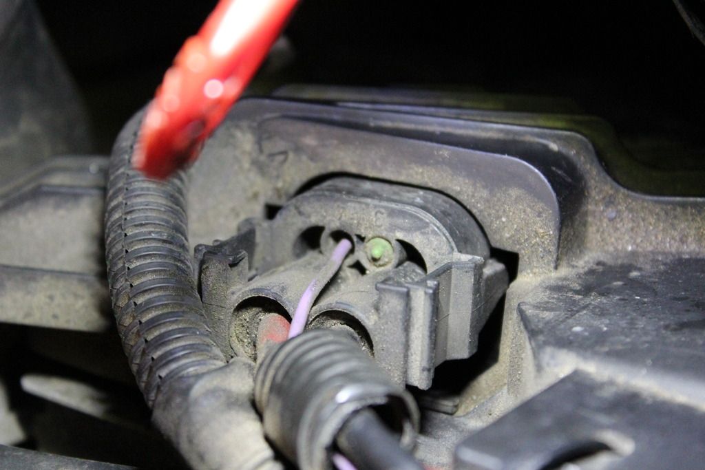
Anyhow, I finally traced it down to a tiny purple wire with a knicked section of insulation. The copper had corroded & I'm guessing the electrical signals that were needed to pass through it were getting intermittently interrupted.
You'll know it immediately if there is a small section of this purple wire that has green corrosion on it.
Cut out this small 1/2" section of wire, soldered in a new section, checked the rest of the length that runs across the top of the radiator & replaced the plastic sleeving and cleared codes (disconnected batt & held + and - leads together). For me this eliminated the problem, hope you have similar luck.
I didn't see anything about that in your post, but I'll share what I found with ours & how I fixed it.
My cheap Autel OBD/CAN scanner won't link up to our 06, but it will on both of our 04's, so I wasn't able to see what it was trying to tell me.
Anyhow, I finally traced it down to a tiny purple wire with a knicked section of insulation. The copper had corroded & I'm guessing the electrical signals that were needed to pass through it were getting intermittently interrupted.
You'll know it immediately if there is a small section of this purple wire that has green corrosion on it.
Cut out this small 1/2" section of wire, soldered in a new section, checked the rest of the length that runs across the top of the radiator & replaced the plastic sleeving and cleared codes (disconnected batt & held + and - leads together). For me this eliminated the problem, hope you have similar luck.
2001 V70XC 200k
2004 V70 AWD 174k
2004 V70R M66 147k
2004 XC70 361k
1995 F250 7.3PSD 262k
2014 Ram 3500 DRW 116k
2004 V70 AWD 174k
2004 V70R M66 147k
2004 XC70 361k
1995 F250 7.3PSD 262k
2014 Ram 3500 DRW 116k
-
- Similar Topics
- Replies
- Views
- Last post