Login Register

TCV Routing Confusion: red = turbo, and blue = fresh air?

Help, Advice and DIY Tutorials on Volvo's P80 platform cars -- Volvo's 1990s "bread and butter" cars -- powered by the ubiquitous and durable Volvo inline 5-cylinder engine.

1992 - 1997 850, including 850 R, 850 T-5R, 850 T-5, 850 GLT
1997 - 2000 S70, S70 AWD
1997 - 2000 V70, V70 AWD
1997 - 2000 V70-XC
1997 - 2004 C70

This topic is in the MVS Volvo Repair Database » Turbo Control Valve and its Correct Hosing Routing
Post Reply
oh-la-la
Posts: 90
Joined: 11 May 2010
Year and Model: 95 855 T5/97 850R
Location: SF

Volvo Repair Database TCV Routing Confusion: red = turbo, and blue = fresh air?

Post by oh-la-la »

Hi guys,
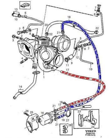
I have searched for TCV diagram for my 95 Volvo 850 T5 but getting confused with these 2 diagrams. When i look at both of my cars the wastegate actuator has been marked yellow and also the vacumm hose has a yellow sticker on it. That makes sense if i follow the frist diagram, yellow line will go to the top port of TCV but! the second diagram showing the wastegate vacumm hose must run to the buttom port of TCV. So, this making me confused which diagram should i follow?
Thanks guys for your helps.
TCV and frist diagram, yellow wastegate hose goes to the top port
Image
Image

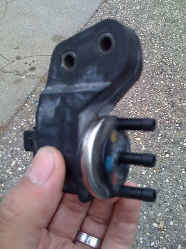
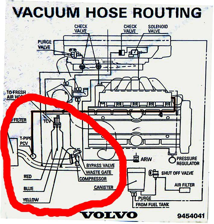
Second diagram the wastegate actuator hose must run to the buttom port of TCV
Image
Image

jblackburn
MVS Moderator
Posts: 14043
Joined: 8 June 2008
Year and Model: 1998 S70 T5
Location: Alexandria, VA
Has thanked: 9 times
Been thanked: 19 times

Post by jblackburn »

I think they kept it the same between the years - yellow should go to the wastegate, red to the turbo, and blue to the fresh air hose.

The turbo control valve on my S70 is shaped a little different, but is set up in exactly the same way.
'98 S70 T5
2016 Chevy Cruze Premier


A learning experience is one of those things that says, "You know that thing you just did? Don't do that."

mercuic: Long live the tractor motor!

oh-la-la
Posts: 90
Joined: 11 May 2010
Year and Model: 95 855 T5/97 850R
Location: SF

Post by oh-la-la »

jablackburn wrote:I think they kept it the same between the years - yellow should go to the wastegate, red to the turbo, and blue to the fresh air hose.
Thanks for your help! Then i should stick with the frist diagram?
Actually i have run with both setups. Routing with frist diagram will give slightly more boost and boost spikes up and settles back between each gear shifts while the second diagram will give slightly lower boost but stays constantly between gear shifts.
So which one sounds normal for you guys?
Thanks again
Image

thecheat
Posts: 533
Joined: 9 July 2010
Year and Model: 1996 850 Turbo Wagon
Location: Sunrise, FL

Post by thecheat »

I wonder if the differences in the top and bottom hoses affecting boost is similar to how the aftermarket turbo valves for the mk4 vw 1.8 turbo work if you reverse the valve. Nothing much changes except the noise of the valve opening because it still acts as an on off switch but the airflow is changed if it is reversed.

oh-la-la
Posts: 90
Joined: 11 May 2010
Year and Model: 95 855 T5/97 850R
Location: SF

Post by oh-la-la »

Even diagram from this pdf file also get mixed up between page 2 vs page 4 and 5
What is this!
Attachments
hose.pdf
(63.83 KiB) Downloaded 1512 times
Image

jblackburn
MVS Moderator
Posts: 14043
Joined: 8 June 2008
Year and Model: 1998 S70 T5
Location: Alexandria, VA
Has thanked: 9 times
Been thanked: 19 times

Post by jblackburn »

I think it's normal for it to spike a little bit on shifts (maybe up 2 psi or so). The CBV then recirculates the extra boost. I only had a boost gauge I borrowed for a couple days from a friend while I was trying to figure out what was going on with my car.
'98 S70 T5
2016 Chevy Cruze Premier


A learning experience is one of those things that says, "You know that thing you just did? Don't do that."

mercuic: Long live the tractor motor!

SimLyons
Posts: 806
Joined: 3 April 2011
Year and Model: 2001 V70 T5
Location: Newberg, OR (Portland)

Post by SimLyons »

Yeah, I'm also confused. Justin, this is the thing I was trying to describe that mounts on the bottom of the air filter housing. It has 3 vacuum hoses and an electrical connection. The blue hose, center, should go to the air intake piping, above the Turbo is that correct? and the electrical connector comes from some loom somewhere. I still have to find that one.
Sim

SimLyons
Posts: 806
Joined: 3 April 2011
Year and Model: 2001 V70 T5
Location: Newberg, OR (Portland)

Post by SimLyons »

Oh...and one of the drawings shows a blue center hose. Goes to the fresh air intake piping whatever that device is. That's where I put the center hose and hope all the pothers got connected well enough.
Sim

ojdorson
Posts: 322
Joined: 14 June 2010
Year and Model: 850R, 1996
Location: Chicago, IL
Been thanked: 3 times

Post by ojdorson »

The two diagrams say the very same thing. The problem occurs in the second image where the "artist" made color choices that don't match the markings on the BCS. Here is the image properly colored.
Turbo-proper colors.jpg
Turbo-proper colors.jpg (63.49 KiB) Viewed 14216 times
Of course, the BCS pictured is "upside down" compared to the one in your hand in your picture.

SimLyons
Posts: 806
Joined: 3 April 2011
Year and Model: 2001 V70 T5
Location: Newberg, OR (Portland)

Post by SimLyons »

I was getting frustrated looking for the cause of relatively low boost after doing all the other stuff. Today I did the "sea-foam" treatment into the intake as described by Justin. Lots of smoke and nice smooth engine, but no joy on boost. Same "80%" of what should be.

So back to the garage and off with the intake so I could see. Yep! A hose not connected to anything! It's from the turbo by-pass valve. I can't find where it is supposed to connect on the other end! (I hope not to the intake manifold....I did connect that before replacing the manifold. Broken hose?). Help!! (Again!!)
Sim

Post Reply
  • Similar Topics
    Replies
    Views
    Last post