Login Register

FMIC on the way! (Future FMIC install thread)

How to go faster, stop quicker, and turn harder. Chips, exhaust, larger turbos, bigger/slotted/drilled rotors, high performance brake pads, manual boost controllers, performance shocks/struts/springs, airbox mods and more! Also discussion on HID and Xenon lights, aftermarket foglights and other exterior lighting.
This topic is in the MVS Volvo Repair Database » Front Mount Intercooler Install
Post Reply
Auburn T5
Posts: 86
Joined: 11 May 2007
Year and Model: 1999 S70 T5
Location: Birmingham, AL
Been thanked: 2 times

Volvo Repair Database FMIC on the way! (Future FMIC install thread)

Post by Auburn T5 »

Monday I ordered a precision turbo FMIC

http://www.spoolinperformance.com/preci ... -p-65.html

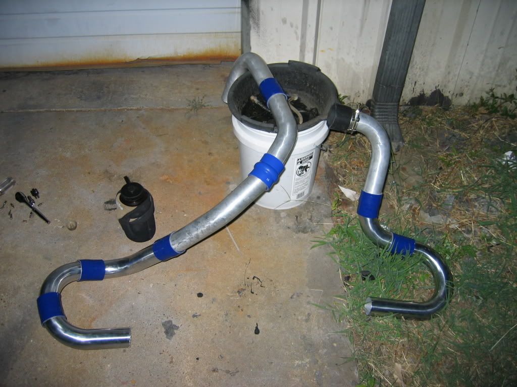
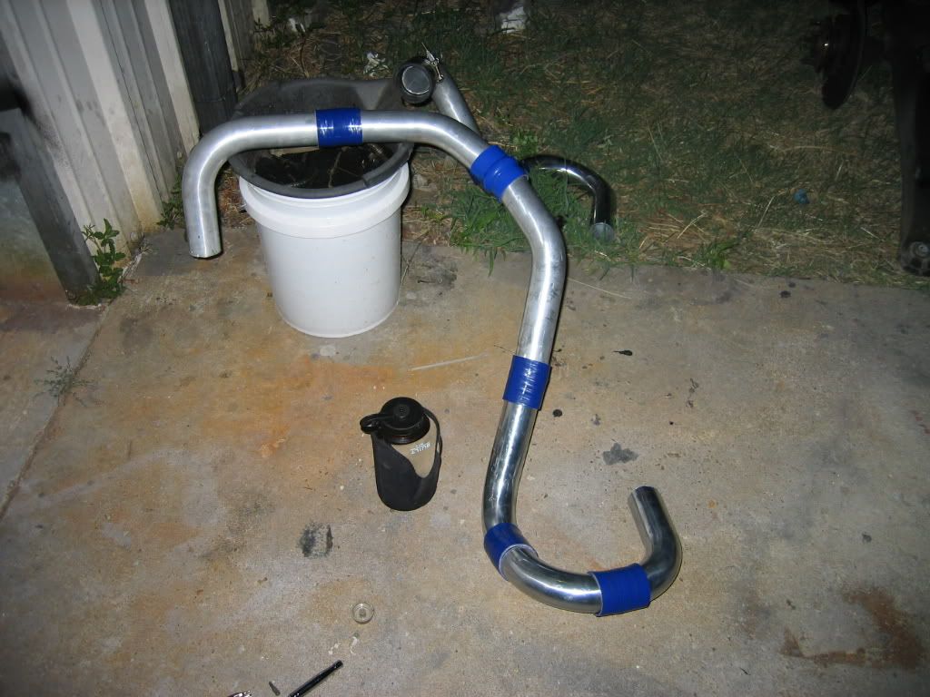
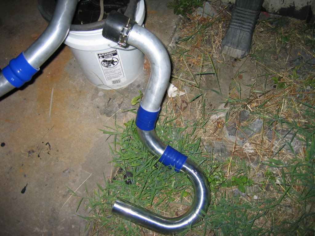
And yesterday I talked to a local guy who supplies all the guys in town with intercooler piping. Reason I went went to him is because although the Ebay kits look affordable, I'd have to add several extra pieces at extra cost to get all the bends and sections needed.

I spoke with a few guys who have FMIC's installed on their S70's and have given me a fairly definitive parts list.

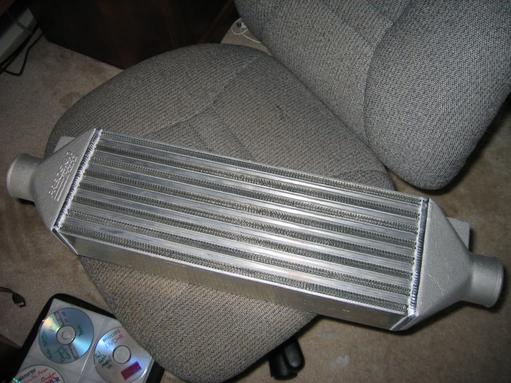
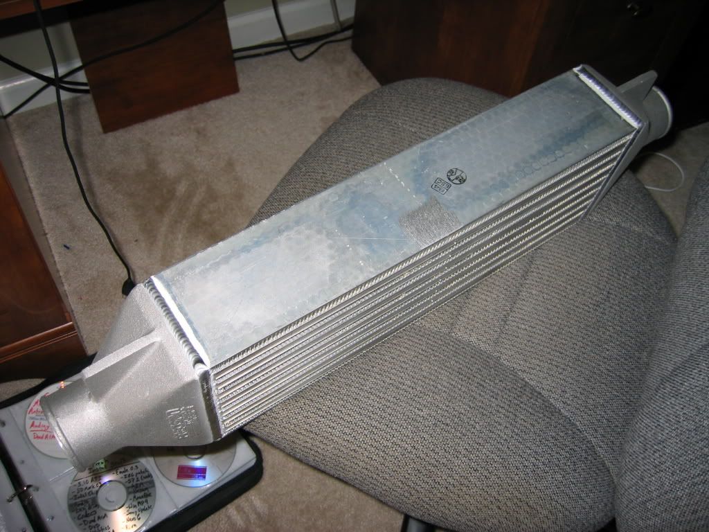
the piping, couplers, Tbolt clamps, reducers, etc totals $180 and no shipping since it's local.. ebay kits are like an extra $40 shipping. The IC was $230 with free shipping from nolimit so just a hair over $400 in parts.

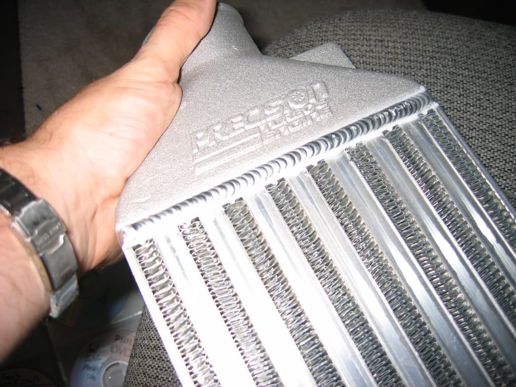
I was close to getting a treadstone intercooler and while they claim to support more power for the money, the precsision IC's have a much higher quality from what I've been told and are better engineered. Besides, I don't plan on making over 350 whp any time soon anyways so this will do well... and when I do an engine build, the wife's T5 will get my IC setup.

I'm super stoked about this. Heatsoak is absolutely atrocious down here in Alabama. My car gets like an extra 20 hp it seems when it's cooler out. Piss poor factory IC flow and little to no actually cooling probably doesn't help either :roll:

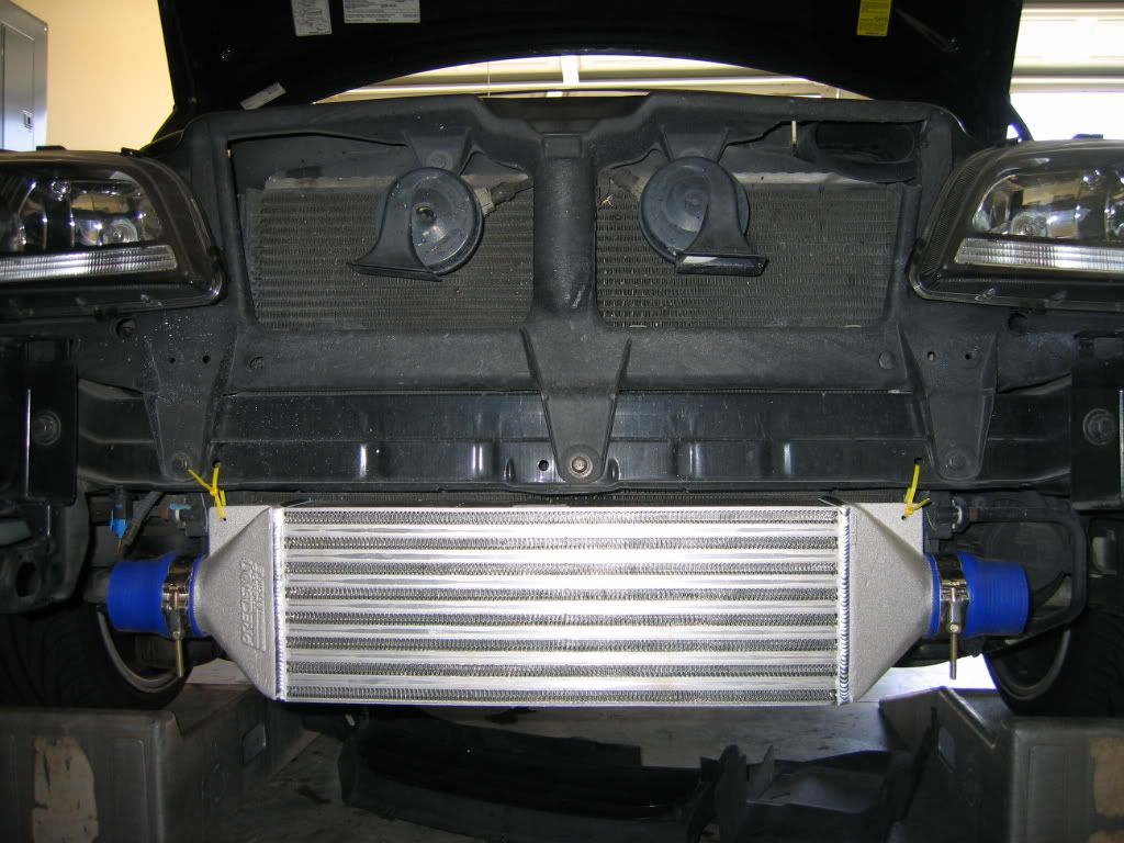
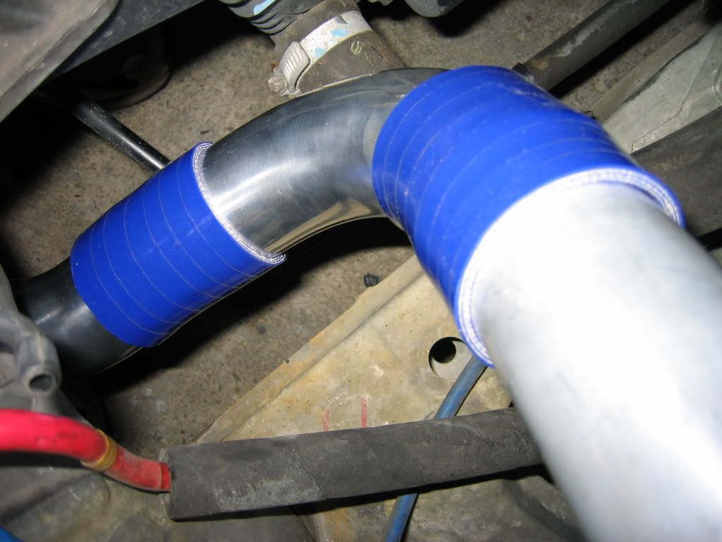
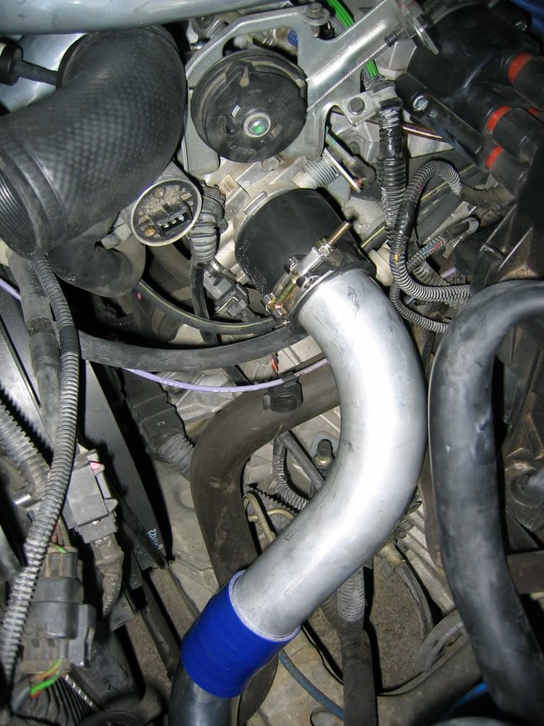
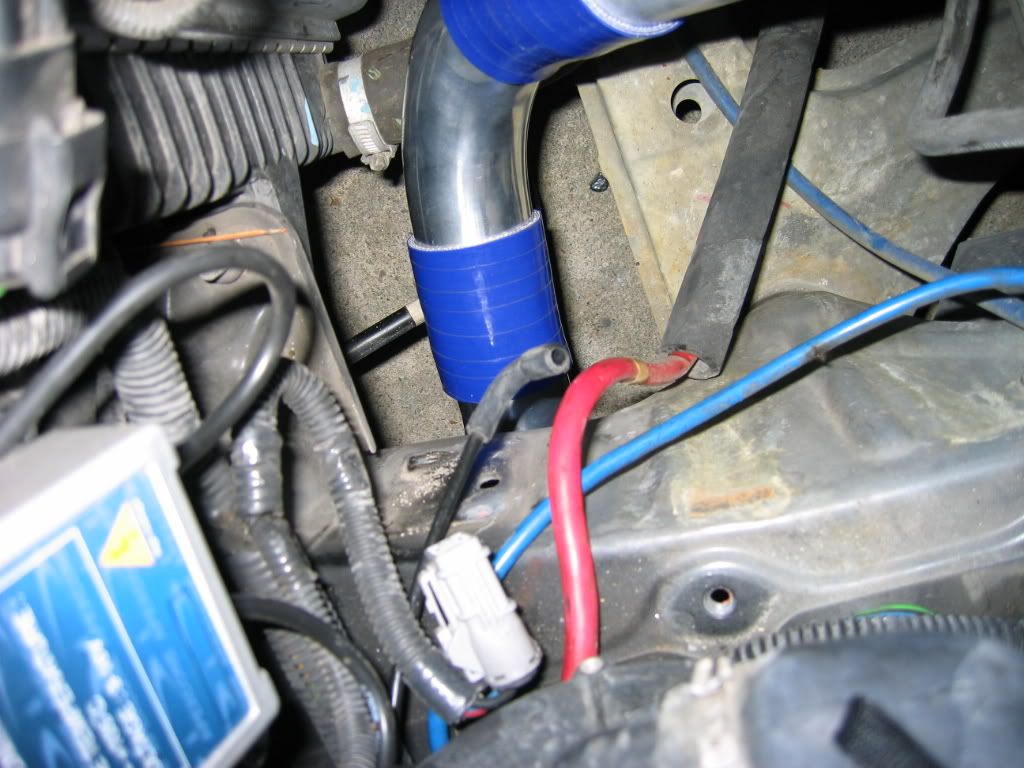
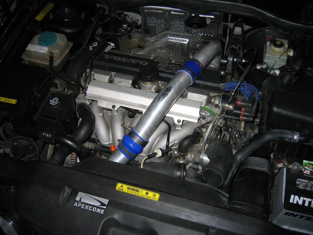
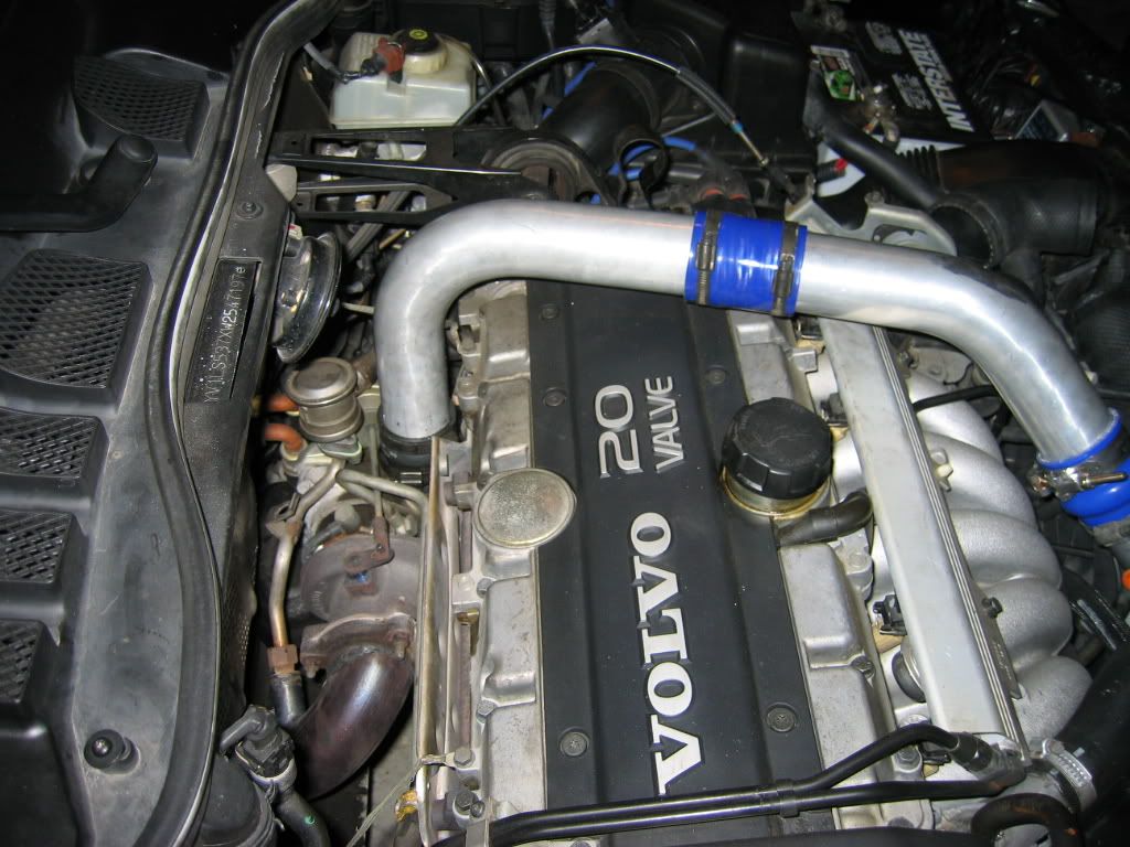
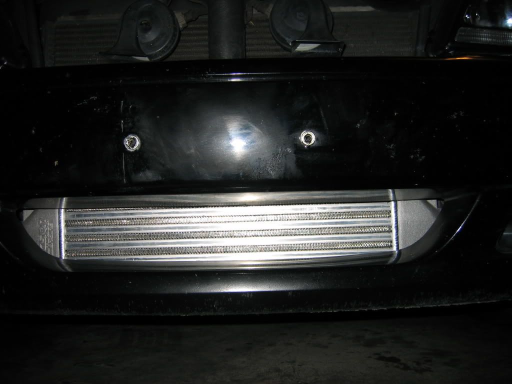
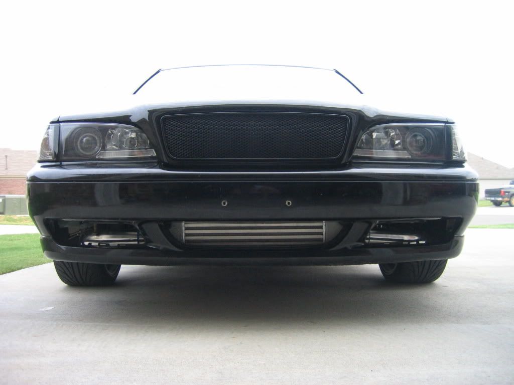
Installation will go down MABEY this weekend if the IC gets here which hopefully it will. Gobs of pictures and instructions will also follow as I hope to put together some semi defnitive guide on everything needed and detailed instructions on install for all the 850 and pre 99 S/V 70 guys as I think everything is pretty much the same.

Also, hopefully a before and after dyno test will be done although I think the real performance measure will be on the road where air is blowing across it.

Stay tuned gang.
Last edited by matthew1 on 24 Dec 2015, 15:57, edited 1 time in total.
Reason: spoolinperformance.com link added, the old one was 404
2020 - Tesla Model 3 Performance
2020 - XC60 T5

1999 S70 T5 - Bilstein touring shocks/struts, B&G S2 springs, OBX full exhaust, other misc. stuff

User avatar
matthew1
Site Admin
Posts: 14463
Joined: 14 September 2002
Year and Model: 850 T5, 1997
Location: Denver, Colorado, US
Has thanked: 2652 times
Been thanked: 1240 times
Contact:

Post by matthew1 »

AT5,

Cool! (pun intended). Thanks for the post, I'll be following this.
Help keep MVS on the web -> click sponsors' links here on MVS when you buy from them.

Also -> Amazon link
. Click that when you go to buy something on Amazon and MVS gets a cut!

1998 V70, no dash lights on

1997 850 T5 [gone] w/ MSD ignition coil, Hallman manual boost controller, injectors, R bumper, OMP strut brace

2004 V70 R [gone]

How to Thank someone for their post

Image

Harleyvh
Posts: 36
Joined: 1 October 2006
Year and Model: 2011 S60 T6 AWD
Location: Lachine, Qc

Post by Harleyvh »

Interesting indeed

Any FMIC Guide for P2 models out rhere?

thanks

Auburn T5
Posts: 86
Joined: 11 May 2007
Year and Model: 1999 S70 T5
Location: Birmingham, AL
Been thanked: 2 times

Post by Auburn T5 »

What's P2?

Anyways, lookie what showed up! 8) Piping guy called and said the pipes and all the misc connectors were delivered to the shop that we're installing it at so once I figure out when we have an evening this week or next free, install will go down.

Image

Image

Image

Image
2020 - Tesla Model 3 Performance
2020 - XC60 T5

1999 S70 T5 - Bilstein touring shocks/struts, B&G S2 springs, OBX full exhaust, other misc. stuff

Auburn T5
Posts: 86
Joined: 11 May 2007
Year and Model: 1999 S70 T5
Location: Birmingham, AL
Been thanked: 2 times

Post by Auburn T5 »

It took about 6 hours of sort of figuring stuff out as I went along but everything came together nicely and everything is running great.


Referring back to the other picturs I posted, the only things not pictured that were needed were a few extra T bolt clamps and a 2.5" to 2.25" reducer for the throttle body. I thought it was 2.25" but it's a little bigger :? I'm using a 2" plumbing coupler at the moment I got from Homedepot until I can make it back out to the shop to get my reducer. It's working but not holding tight on the TB (more on that later) Also not pictured is one of those little aluminum nipples that would be welded to the piping right at the throttle body inlet for the air idle control hose to plug into. No one locally has them and I couldn't wait to have one shipped so I got a brass plumbing 1/2" to 3/8" union as I wasn't sure what the inner diameter of the IAC hose was. Turns out it's 1/2" so what I did was took a drill and drilled out the inside of the piece to a single diameter as it get smaller at the 3/8" end. After that, I took a 1/2" drill bit and drilled a hole in the IC pipe right at the TB connector. The hole was a little too small to screw the brass fitting in so I used a dremel grinding stone to lightly grind a little bit more out. Just enough to screw the brass fitting in. It was extremely tight but not wanting to take any chances, I coated both the inside joint and outside where the brass fitting screws in with a couple of layers of JB weld. It doesn't look too pretty but it will do until I can get an aluminum nipple to have welded on in place of the brass fitting.

So when you're ordering your piping, try and get the aluminum nipple piece to weld onto the pipe to save yourself that headache. It wasn't hard just a lot of work.


Anyways, moving along...

The bumper removal was easy. Drilled out the 4 rivets holding the wheel well liner to the back of the bumper. (turn the wheels to get a good angle on the rivets.

Next I removed the splash guard. 2 screws hold it in and a small tab on the back of it releases it.

After that, I used a torx bit to remove all the screws holding a second plastic guard piece to the bumper.

After that, there will be 2 large bolts to remove. It uses I think a 15mm socket. They're the only ones that big so they're hard to miss. Mine put up a fight so I had to pop out the plastic pieces in the bumper that are next to the fog lights and use a breaker bar to break them loose. I was rewarded by tons of the most disgusting rusty muddy sludge water pouring out of the bolt hole as I loosened the bolt. I recommend sitting on teh ground in front of the bumper when doing this and having a towel below the bumper in case this happens to you.

So after those bolts were removed, (and the fog lights are unplugged) the bumper slides straight off. If it doesn't come off, you probably missed a couple of torx screws.

After this is done, remove all the factory intercooler piping along with the snorkel that connects the air box to the air inlet at the front of the air dam.

At this point, the battery needs to be removed. Following that, there are 2 large screws holding the battery tray to the frame and 2 smaller screws on the top of the battery tray holding the cruise control module. Remove these and the cruise control module under the battery tray can be removed. Unplug it's power connector and vacuum line and set it aside.

Now, for the air pump, it's no secret that it has to be removed from it's factory location in order for the cold side of the IC piping to get to the throttle body so before I decided whether or not to totally remove it or leave it, I unbolted it and moved it up to where the battery tray used to be.

In this pic, one of the bolts holding it to the frame is partially out and the bolt just above it is the 2nd one. Remove both of these to free the air pump.

Image

The final obstacle is the tow hook. This had to be removed to get the hot side of the piping around the black AC canister and up to the turbo so we used a plasma cutter to eat through it. It can probably be done with a reciprocating saw (sawzall) or even a dremel but the metal in the hook is extremely strong and would take forever with a dremel. So if you know of any shops (most exhaust shops) that you cold drive the car to and have them cut the hook off, it will save you a lot of time.

Once this was out of the way, it was time to mount the intercooler. I'm not sure if all the cars have them or not but there are 3 screw holes in the frame right where the IC is mounted that I was able to thread a couple of zip ties through (drilled a hole in each mounting bracket on the intercooler) and get an easy mock up location for the IC.

Image

Now it was time to start playing with the IC piping to see what would need to be done.

At first, it may seem like there isn't enough piping but as Mark (BlackT5 on the volvospeed forums) said, the pipes can really only go one way and going that one route from turbo to throttle body, it WILL be enough piping unless you screw up so pay attention as I explain where the pipes were cut.

Starting at the turbo, a 90* bend comes over the engine (a la RIP kit) to a pair of 45* bend pipes.

The first pipe connecting to the turbo, I cut about 2 or 3 inches off the end so that it didn't sit so high over the engine. The hood wouldn't close all the way with it sitting that high so I had to remove enough to let the hood close but not so much so that it laid down on the engine.

The 45* piece coming after that had a little cut off from each end and the second 45* piece had a little cut off of the end that connects to the first 45* pipe. I made these cuts last becuase I started running the pipes from the intercooler.

From the passenger (hot) side of the intercooler, I used a 180* J pipe. I cut it in half directly in the center of the bend becuase that U has to be extended out wider to wrap around the black AC canister (I have no idea what it's technically called but I'm sure someone will enlighten me). Seeing as to how Sam was busy getting his car ready for the SE turbo bricks meet that starts in about 6 hours, he didn't have time to weld up a piece of the extra pipe that was cut from the other pieces into that U to extend it out so I used a silicone coupler. It got the job done until we have a free weekend to weld a lot of these together.

The J pipe end that goes into the intercooler's coupler had a little bit cut off so that it didn't extend out so far past the black AC thing. I cut enough of it off so it gets closer but not too close. I don't have a picture of the hot side of my piping but I used Mark's picture below for a reference.

Image

Ok. After that bend is made, I took another J pipe and cut it in half at the center of the bend. Here comes the hard part. Getting the piping up from that U bend up to the 45* piece going to the turbo requires some elbow grease, a little wire moving and lots of PATIENCE.

What I did was try to get that J down to the U from above. It became apparent that the wiring harness that's in that plastic sheath type thing is the biggest obstacle. There's also what appears to be a fuse or some sort of connector in white plastic attached to a little bracket on the front of the alternator. This was in the way so I popped it out of the metal bracket and tucked it back against the back of the alternator and bent the metal bracket holding it away to free up some precious space.

At this point, I decided to try from below to get the J pipe through the space and it worked. It's an EXTREMELY tight fit and attached a silicone sleeve to the end of the J as I knew once the pipe was in, it'd be impossible to get it on when it was down in the tight space. Removing the little air hose connecting to the ECU box helped and also pull out the oil dipstick as the handle will get in your way (or at least it got in my way).

No cuts at the top of the J pipe nor at the jointing piece of that 45* pipe were made. This pic shows where my coupler ended up and how the 45* piece fit to it.

Image

Image

Image

After that J pipe is in place and the end of the J (at the curve) is in the silicone copuler coming from the U, it's time to get the end of the first 45* pipe into the connector at the end of the J pipe. This is the other hard part. It took some work and elbow grease to get it in. There are a lot of stiff hoses that won't move very much but it can be done. The 45* bend on mine bends right in front of the dip stick.

Image

After that is in, you can breathe easy as the rest of the install is a walk in the park. Mark gets a cookie with teh whipped cream and a gold star for figuring out how to get another 1/4" of piping up through that area. I saw no way to do it without moving the plastic sheath that held the wiring.

At this point, I made the cut at the 90* pipe that attaches to the turbo and then fit it into the coupler on the turbo. Then I fit in the other 45* pipe connecting to the 90* pipe to see how much would need to be cut from the 45* pipes to give a nice snug fit that wasn't bowing out or causing wierd fittings in the silicone couplers. I could have probably gotten away without cutting them but they wouldn't have had a solid fit in the silicone couplers so I cut enough off the ends of them to get a nice snug fit. Play around with them and you'll see how much needs to be cut.

Now for the cold side of the piping.

Coming out of the intercooler, another J bend 180* pipe. I don't think I cut this piece at all. The next piece will be a small L shaped piece of pipe that was left over from the J pipe that was cut that was manipulated up next to the alternator. So use that little right angle piece to point up towards the throttle body. The final piece will be your other 90* pipe. Quite a bit was lopped off of one side as very little pipe is needed at the coupler that attaches to the throttle body. This 90* piece's long section of pipe should reach down and fit easily into the coupler on that small 90* angle piece.

And that's it. Here are pics of the cold piping.

Image

Image

Image

Image

At this point, all the piping should be mock fitted up. Check the coupler connections to make sure all the pipes going in and out of them aren't at radical angles going into them. You obviously want the pipes to be as straight as possible when connecting together.

The last part will be attaching all the pipes together. I found the easiest way to do this was to remove the piping in sections so I wouldn't forget which pieces went where. I started by removing the 90* pipe coming from teh turbo and the two 45* pipes attached to it. I used my hump connector joining the two 45* pieces. At this point, I realized that I didn't have enough Tbolt clamps so I re-used some of the worm type band clamps.

Then I removed the J pipe that sits next to the alternator followed by the U bend going into the intercooler.

On the cold side, I pulled the pipe going to the throttle body followed by the 90* angle and J pipe going into the intercooler.

This is what all the piping looks like out of the car. Hopefully it will illustrate how all the pipes attach and which pipes go where.

Image

Image

Image

After I took these pictures I started attaching clamps to the couplers and loosely tightening them.

The most helpful tip I can give as far as getting the J pipe and 45* pipe that run in front of the intake manifold clamped together is to put the coupler on the end of the J pipe where it meets the 45* pipe and use a worm clamp and tighten it down hard. Then slip a second worm clamp on and once the U bend coming from the intercooler is mounted up, fit the J pipe up back into position and clamp it down hard into the end of the U bend so it can't move.

Take the end of the 45* bend (this end had a bead on the end) and wrestle it down back into the silicone coupler. Before tightening that 2nd worm clamp, I attached the 90* bend at the turbo and the other 45* bend, shifted them around into position and then started at the turbo, tightened that clamp down and then tightend the joint there at the first 45* pipe then made sure the 45* pipe at the J bend joint was nice and straight then tightend that band clamp and then the 2 clamps at the hump connector. That should take care of all the piping on the hot side.

The cold side is fairly self explanitory as none of the pieces require any specific order of tightening.

Once it's all tight, I moved the air pump and sort of laid it down on the piping there at the small 90* bend up to the throttle body and laid the cruise control module next to it. It will be messy if you leave it like this but at the moment, I see no other real option. I laid the battery tray on that and then put the battery back in, attached the air idle control hose to the brass nipple, clamped it down and fired it up.

Here's the rest of the pics I took.

Image

Image

Image

Image

You can see that the hood fire shield thing is polishing that 45* pipe and I had to bend down the little bracket that used to hold the factory IC pipe as it was rubbing it also.

The last part will be putting the bumper back on. I had to remove my fog lights as they were hitting the piping. That was simple and getting the bumper back on was easy also. It slides back on on those two white guide tracks. I had a friend push the bumper forward a little to line up the bolt holes.

As far as driving impressions go, I'm very pleased. Sam followed me home as he lives about a mile from me to be there in case something went wrong (which it did). I got into boost once and blew a hose off. Rest assured, if you didn't tighten any clamps tight enough, the boost will be more than happy to show you where you didn't get them tight enough.

I re-attached the hose, tightened it up and drove home without getting back into boost.

This morning, I went back over all the couplers with the ratchet and made sure they were all totally tight and took it out for a spin. First thing I noticed was the increase in power in the mid range. It feels like it pulls harder in the mid range RPM's and lag isn't nearly as apparent. It spools into boost much quicker now. that jump in 2nd and 3rd gear from 5 to 10 psi is nearly instantaneous where as before I could watch it slowly creep up to 10~12.

At the moment, I'm still using that plumbing attachment. It holds but barely. I'm going to pick up the reducer hose this afternoon becuase the rubber is heating up and getting spongy and the boost is pushing it off the TB no matter how tight that clamp is on there. I stripped one clamp trying to get it nice and tight so it looks like the heat is causing it to get mushy and the boost is pushing it off. Watching the boost gauge, It will jump up quickly to 12psi and then just as quickly slump back down to 10 and hold steady at 10.

I'm not sure if it's just spiking to 12 or if the slipping hose at the throttle body is preventing it from staying at 12. The rest of the clamps are all extremely tight so I'm 99% confident that they're not leaking.

So, anyways, that's about it. It's definatly something I'm glad I took the time to do as unpleasant as that hot piping was to figure out, hopefully I've shed enough light on the situation that you guys wanting to do this will have a bit more info to help you out than I had. I'm not sure if the ME7 guys can use all this or not but hopefully at least some of it will help.

I didn't have to cut the frame or bumper or anything like that to get the IC to fit or to get the bumper to fit back on. Whether or not you'll have to or not, I'm not sure. If you use the same IC or one with similar dimensions, you shouldn't have to. The precision IC's are top quality and although they look small, I've talked with several guys who are gurus on turbo applications and they say the precision units are top quality and will greatly outperform the cheap Ebay IC's. Whether or not it will matter at the low HP most of us make or not, I'm not sure but one of the guys at the shop I did the work at has a beast civic that puts down over 500 whp. He originally had an ebay intercooler and switched to a precision IC that was a little smaller and made an extra 60 hp.

Tonight I'll be going to the track to see if I can drive the car well or not. It'll be the first time taking it to the track so my expectations aren't set high at all. Whatever it runs, that's what it runs :lol:

Tomorrow though will be the big day. We'll be putting it on the dyno and I'll see what sort of numbers I've got. Again, expectations aren't too high seeing as to how the thermometer in the dyno room yesterday was reading 121* F @ 85% humidity :shock:

I'll post updates hopefully at the end of the weekend. Feel free to ask any questions as I'm sure I left out some stuff.
2020 - Tesla Model 3 Performance
2020 - XC60 T5

1999 S70 T5 - Bilstein touring shocks/struts, B&G S2 springs, OBX full exhaust, other misc. stuff

User avatar
matthew1
Site Admin
Posts: 14463
Joined: 14 September 2002
Year and Model: 850 T5, 1997
Location: Denver, Colorado, US
Has thanked: 2652 times
Been thanked: 1240 times
Contact:

Post by matthew1 »

Auburn, did you ever get it to the dyno? How has it been the last few months?

Awesome mod there, just beautiful. And thanks for the pics and writeup. This got under my radar since the summer, but I need followup.
Help keep MVS on the web -> click sponsors' links here on MVS when you buy from them.

Also -> Amazon link
. Click that when you go to buy something on Amazon and MVS gets a cut!

1998 V70, no dash lights on

1997 850 T5 [gone] w/ MSD ignition coil, Hallman manual boost controller, injectors, R bumper, OMP strut brace

2004 V70 R [gone]

How to Thank someone for their post

Image

BackInBlack
Posts: 6
Joined: 29 April 2009
Year and Model: Volvo 850 - 1994
Location: London

Post by BackInBlack »

IMG_7971.jpg
IMG_7971.jpg (135.6 KiB) Viewed 10300 times
In the image you will see the two arrows at which I am referring to.

Where the air intake tube is (Red Arrow), there used to be a piece of plastic attached (Purple Arrow) which looked like to me it was there to stop water entering the airbox (Highlighted Blue)?

I see you have removed/cut yours off, have you had any problems with water entering the airbox?

.....*** I think it is called a snow-guard***.....
'94 Volvo 850 SE - 143BHP - Saloon

Image

98S70T5silverbullet
Posts: 7
Joined: 8 November 2011
Year and Model: S70 T5 98'(400,000KM
Location: Ottawa, Ontario, Canada

Post by 98S70T5silverbullet »

I removed mine and no problems what so ever... no water entering the airbox that is...

SKALARIAK1
Posts: 1
Joined: 7 February 2013
Year and Model: 1996
Location: hawaiian gardens

Post by SKALARIAK1 »

hey man where i can buy the headlights like yours????

RyanT5
Posts: 26
Joined: 4 February 2013
Year and Model: S70 T5, 98
Location: St. Louis

Post by RyanT5 »

I believe these are what youre looking for

http://www.ipdusa.com/products/6956/114 ... -headlamps
Image

Post Reply
  • Similar Topics
    Replies
    Views
    Last post