


VVT hubs install / adjust
-
abscate

- MVS Moderator
- Posts: 35273
- Joined: 17 February 2013
- Year and Model: 99: V70s S70s,05 V70
- Location: Port Jefferson Long Island NY
- Has thanked: 1498 times
- Been thanked: 3810 times
Re: VVT hubs install / adjust
Yeah, i blew that. You leave the pulleyone tooth short to set the limitbolts, not the belt.
Empty Nester
A Captain in a Sea of Estrogen
1999-V70-T5M56 2005-V70-M56 1999-S70 VW T4 XC90-in-Red
Link to Maintenance record thread
A Captain in a Sea of Estrogen
1999-V70-T5M56 2005-V70-M56 1999-S70 VW T4 XC90-in-Red
Link to Maintenance record thread

-
oragex

- Posts: 5347
- Joined: 24 May 2013
- Year and Model: S60 2003
- Location: Canada
- Has thanked: 102 times
- Been thanked: 352 times
- Contact:
Nice DIY, thanks for sharing. That said, this job is not for me... only 50 easy steps
Several Volvo Repair Videos https://www.youtube.com/playlist?list=P ... s0FSVSOT_c
-
cn90
- Posts: 8251
- Joined: 31 March 2010
- Year and Model: 2004 V70 2.5T
- Location: Omaha NE
- Has thanked: 4 times
- Been thanked: 466 times
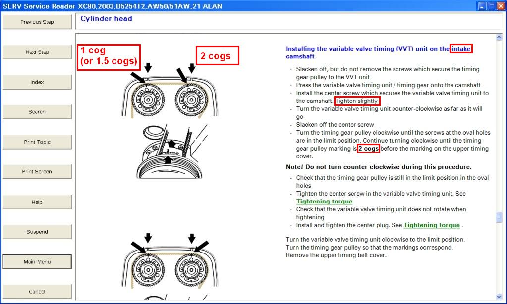
- Actually it is very simple if you think about it: when it is all said and done (like during normal operation), the cam marking lines up with the TB cover, so you cannot turn CW any more than that (cam in retarded position"). But you can turn it CCW (now cam in "advanced position").
- So, look at the VIDA instructions below, which is basically useless, but use it only for markings.
- Finger-tighten the center bolt a bit, this way you can turn the Hub CW until it lines up with the mark on the TB cover, tighten the center bolt a bit more. Now rock the gear back and forth (CCW and CW)...in the CW position, it must line up with the TB cover mark.
- Once you are happy with this relationship, i.e., at full CW turn, it lines up properly, you can now tighten the center bolt to spec. Check the Hub again.
Whatever it is, when all said and done, the cam marking lines up with the TB cover when turned CW.
2004 V70 2.5T 100K+
2005 XC90 2.5T 110K+
2005 XC90 2.5T 110K+
-
vtl
- Posts: 4724
- Joined: 16 August 2012
- Year and Model: 2005 XC70
- Location: Boston
- Has thanked: 114 times
- Been thanked: 604 times
It's not that bad, plus he sheds light on a few gotchas, so you don't have to spend time working around them.
Critical question is tools. I'm not talking about camshaft locking and alignment tool, but good torx bits, good breaker bar, good precise torque wrench, seal puller and installer, etc.
-
MarcM
- Posts: 183
- Joined: 23 September 2015
- Year and Model: 2005 S60 2.5T AWD
- Location: Monadnock Region, New Hampshire
- Has thanked: 1 time
- Been thanked: 3 times
I have all that equipment. Only tools I didn't have, which I recently bought, was a torque angle gauge for the head bolts and the camshaft locking tool.It's not that bad, plus he sheds light on a few gotchas, so you don't have to spend time working around them.
Critical question is tools. I'm not talking about camshaft locking and alignment tool, but good torx bits, good breaker bar, good precise torque wrench, seal puller and installer, etc.
I appreciate people throwing information into the thread. Helpful as usual!
2005 S60 2.5T AWD
IPD mods:
IPD HD PVC intercooler coupler/upper, HD Subframe poly inserts
ProPartsSweden HD top mount square mount, PPS lower torque rod & control arms.
IPD mods:
IPD HD PVC intercooler coupler/upper, HD Subframe poly inserts
ProPartsSweden HD top mount square mount, PPS lower torque rod & control arms.
-
MarcM
- Posts: 183
- Joined: 23 September 2015
- Year and Model: 2005 S60 2.5T AWD
- Location: Monadnock Region, New Hampshire
- Has thanked: 1 time
- Been thanked: 3 times
Well, I lucked out. VVT/CVVT isn't spring loaded. Not too bad (so far). Bought the full cam/crank tool set. Took quite awhile to discover the crank pin tool requires removal of starter and the plug they speak of is behind it. Directions are non-existent per se. Hubs are on. Fiddled a bit to get the hubs so that the slots on the gear are centered to hub bolt holes so there's wiggle room up top.
2005 S60 2.5T AWD
IPD mods:
IPD HD PVC intercooler coupler/upper, HD Subframe poly inserts
ProPartsSweden HD top mount square mount, PPS lower torque rod & control arms.
IPD mods:
IPD HD PVC intercooler coupler/upper, HD Subframe poly inserts
ProPartsSweden HD top mount square mount, PPS lower torque rod & control arms.
-
pdr1966sc
- Posts: 36
- Joined: 24 September 2018
- Year and Model: 2006 V70R
- Location: Ontario
- Been thanked: 2 times
Can I jump in here - I have my cams locked at the back of the engine.
Reinstalling the EXHAUST VVT sprocket - intake was NOT removed.
What I see for the intake VVT is that it is- starting from the mark matching the cover - I can turn clockwise ABOUT 2 teeth or 3 troughs where as to run from TDC counter clockwise it is about 1/2 that.
- would it be a correct to assume that the exhaust should have the similar relationship (slightly more forward than back) travel within the range?
-
cn90
- Posts: 8251
- Joined: 31 March 2010
- Year and Model: 2004 V70 2.5T
- Location: Omaha NE
- Has thanked: 4 times
- Been thanked: 466 times
I need to revisit this issue of confusing VIDA instructions (1 cog, 1.5 cog blah blah blah etc.).
Here are my simple thoughts having done a few VVT Hubs...
1. You must lock the rear camshafts, search forum for tools (ebay vs home-made).
People here recommend CTA brand, so this is what I use.
Do NOT over-tighten the bolts on the locking tool, just snug it down and that is it.
2. I can tell you what is confusing:
- The pdf in the above link by "F250", while it was written with good intention, is confusing,
especially when it comes to the 3 adjusting bolts.
- This video below is another confusing video:
---
- Locking the cam is an art, you may have to turn the crank (30-mm nut) back and forth a bit until it is right.
You are talking about 1-2mm here and there on the crank 30-mm nut. Once the camshafts are locked
in the rear: verify that crank marks and cam marks are perfect. Tricks in forum: use white-out paint to help you see these tiny marks.
- For factory setup, no need to mess with the 3 adjustment bolts.
3. Anyway, to recap:
- When it is all said and done, just before you install the timing belt:
* With camshafts locked
* With center bolt (T55) and 3 adjusting bolts gently snugged...
---> The VVT should be able to go CCW and CW, and on full CW, it should line up with the mark
on TB cover. See above video I posted on 07 Mar 2018, this is the single best video on youtube
bc it shows the trick of marking the back side of the VVT hub, this way you don't have to install/remove
the TB cover all the time while checking.
* Once you are happy with the CCW and CW rotation, tighten the center bolt and 3 bolts a bit more.
Check again to be sure nothing has been disturbed, then torque them down:
* Center bolt (T55) is about 85-88 ft*lb.
* The three (3) 8-mm adjusting bolts: ~ 8-10 ft*lb; I use some Red Loctite here.
2004 V70 2.5T 100K+
2005 XC90 2.5T 110K+
2005 XC90 2.5T 110K+
-
- Similar Topics
- Replies
- Views
- Last post