


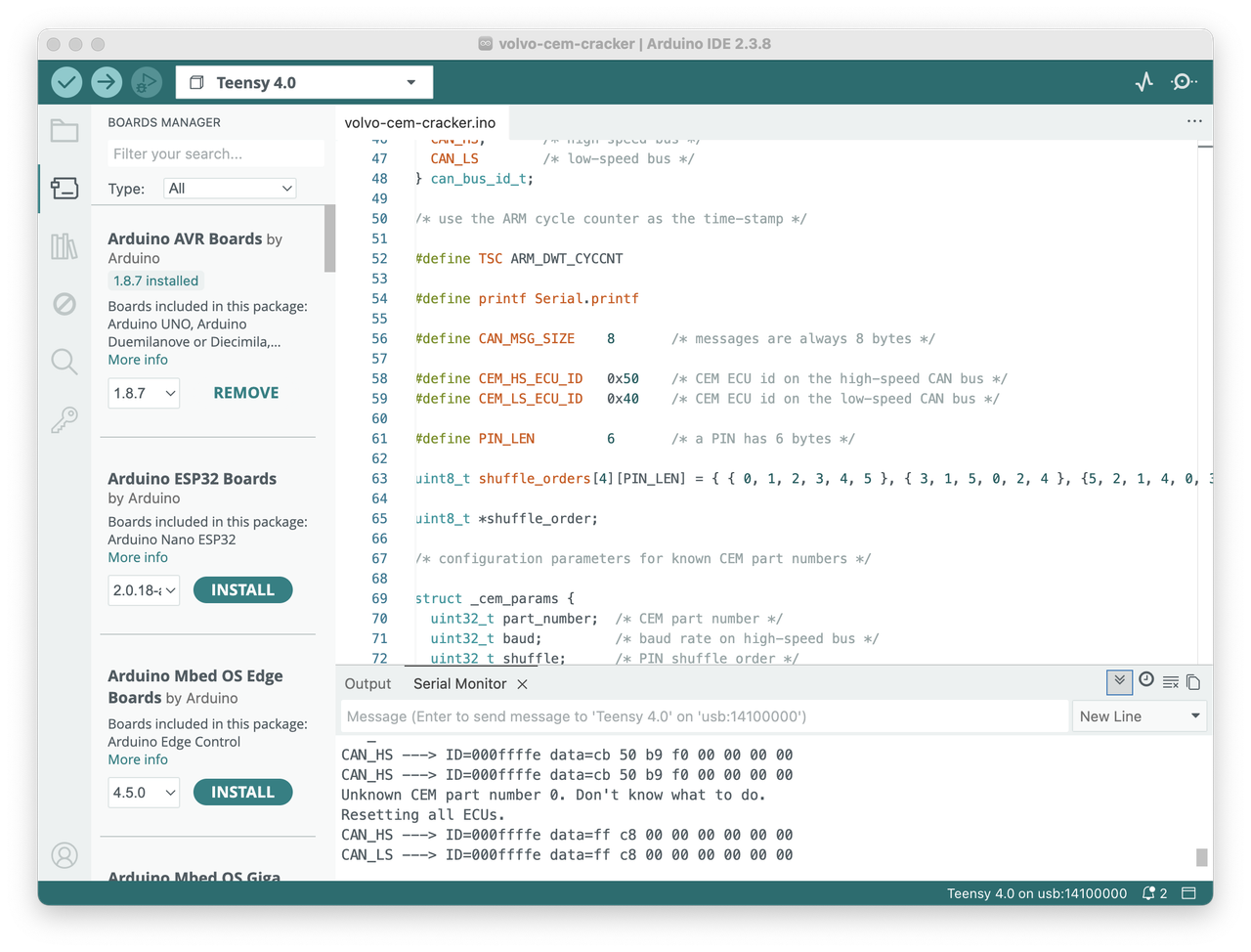
Remove this line https://github.com/vtl/volvo-cem-cracke ... er.ino#L14lookforjoe wrote: 15 Mar 2026, 18:37 Came here via GThub - trying to figure out why Volvo-CEM-Cracker is not working on my 2012 C30T5 - trying top extract the PIN.
I can't find any directions on making changes to the script, if adding a part number is what is required
Anyone on here have experience with this?
Vida CEM swapping
-
vtl
- Posts: 4934
- Joined: 16 Aug 2012, 13:35
- Year and Model: 2005 XC70
- Location: Boston
- Has thanked: 130 times
- Been thanked: 686 times
-
lookforjoe
- Posts: 21
- Joined: 24 Jan 2013, 20:56
- Year and Model: 1991 743
- Location: NY, USA
- Has thanked: 2 times
- Been thanked: 4 times
To continue, after reading one of the posts on here, I rechecked the pinout and continuity on my board & ODBII port, everything matched the schematic.
(EDIT - just saw your response) I also removed the line of code regarding part number check, and still got the same error
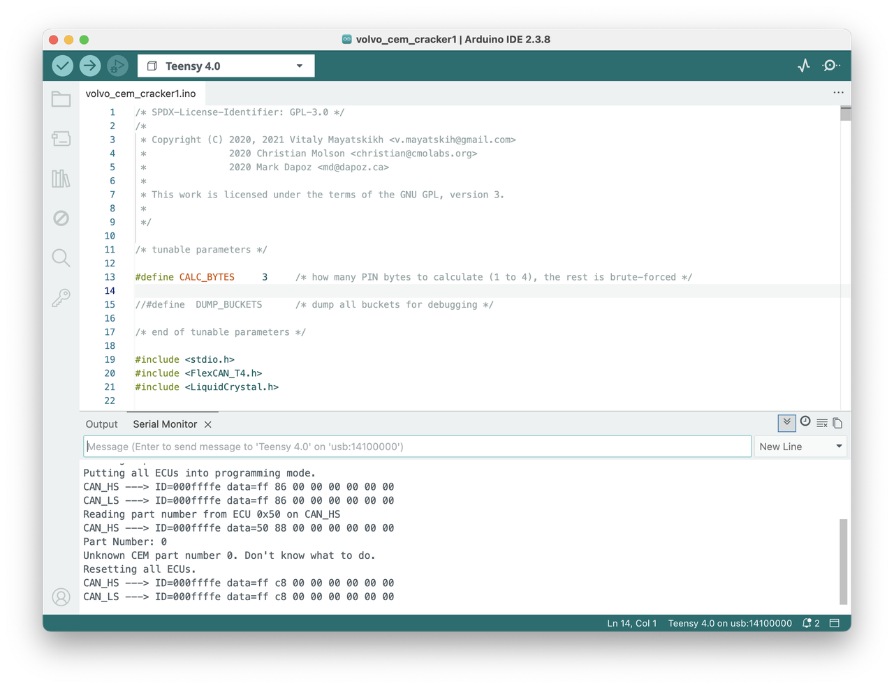
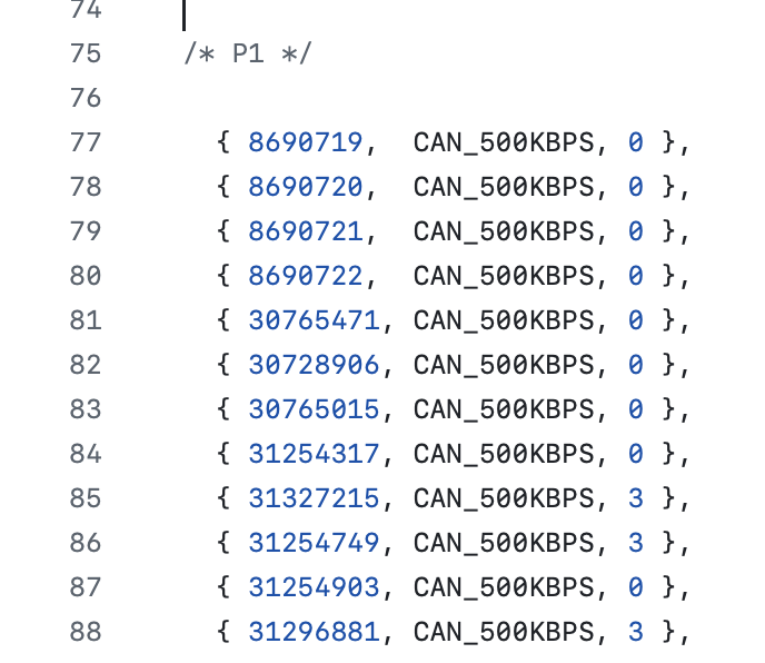
I'll drop the CEM, and check that my PN is on the list
(EDIT - just saw your response) I also removed the line of code regarding part number check, and still got the same error
I'll drop the CEM, and check that my PN is on the list
-
lookforjoe
- Posts: 21
- Joined: 24 Jan 2013, 20:56
- Year and Model: 1991 743
- Location: NY, USA
- Has thanked: 2 times
- Been thanked: 4 times
No, it started & runs just fine.
I had to modify the ODBII port as it didn't have all the wires in the correct locations. Perhaps it is somehow defective, even though the pins all check out with a multi-meter.
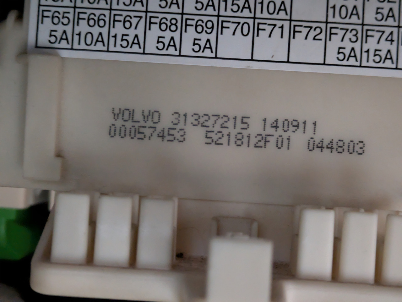
Also, my CEM is a listed number

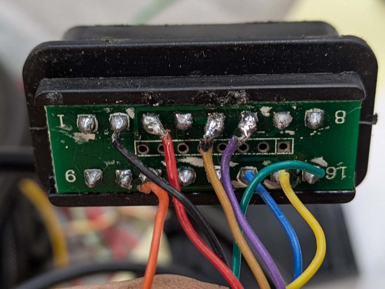
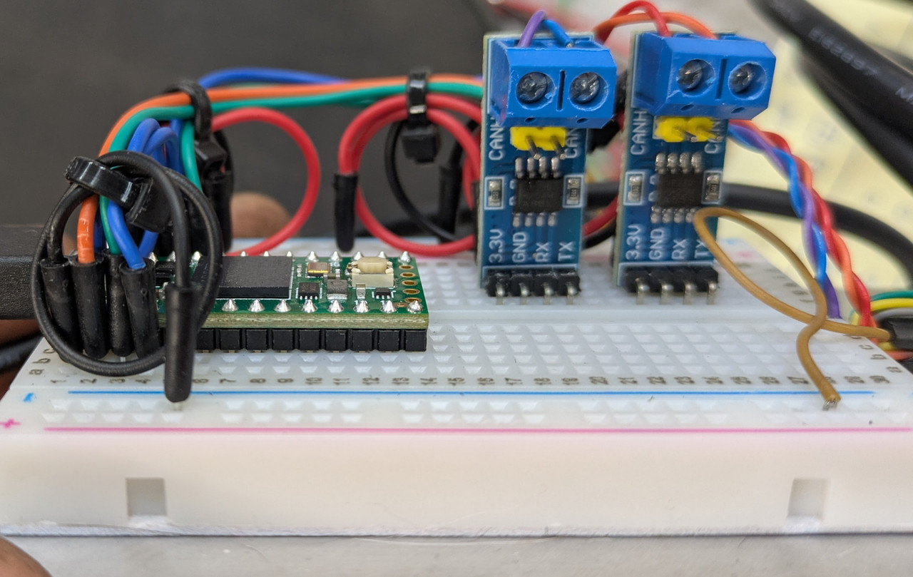
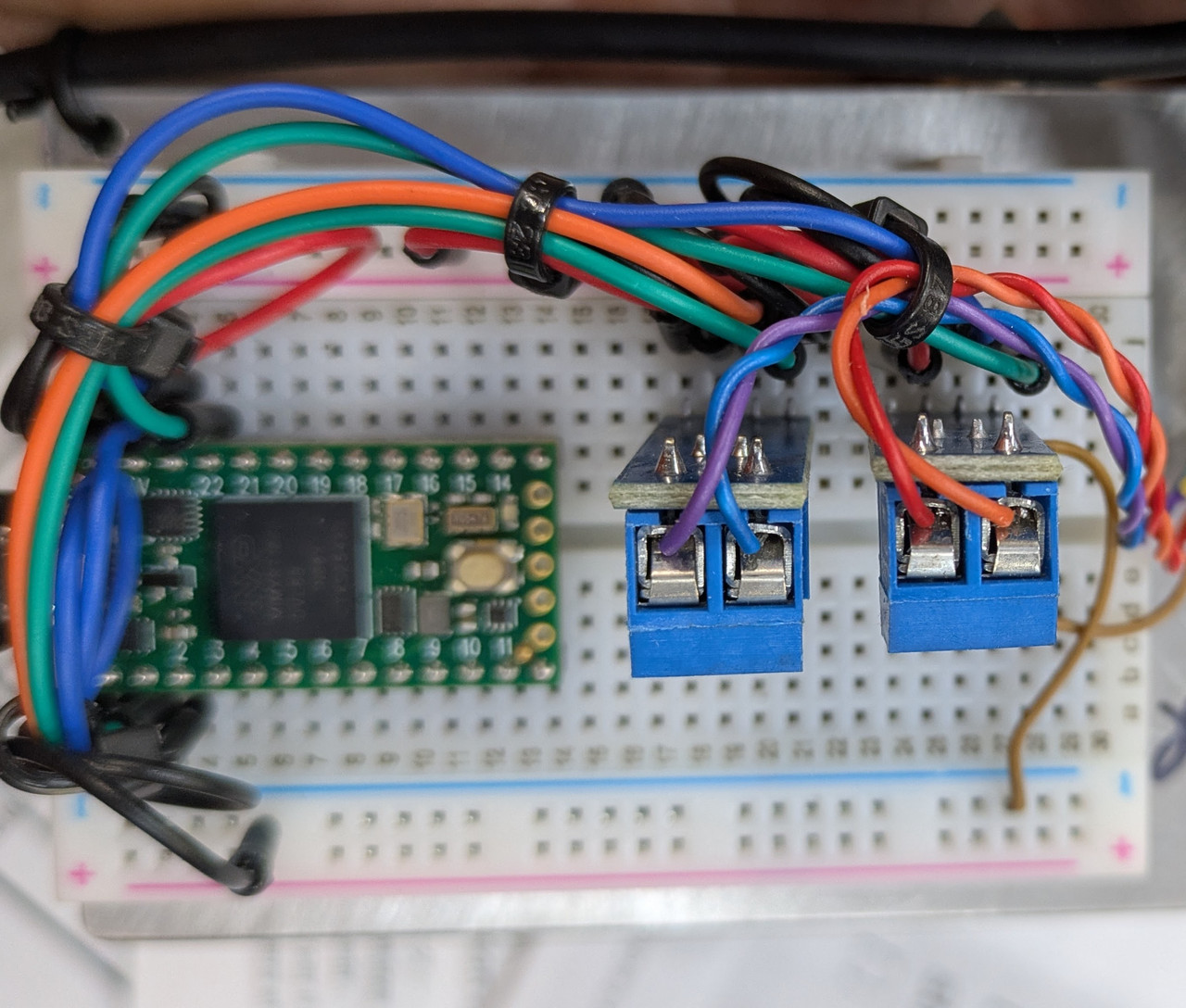
I had to modify the ODBII port as it didn't have all the wires in the correct locations. Perhaps it is somehow defective, even though the pins all check out with a multi-meter.
Also, my CEM is a listed number
Last edited by lookforjoe on 16 Mar 2026, 19:23, edited 1 time in total.
-
lookforjoe
- Posts: 21
- Joined: 24 Jan 2013, 20:56
- Year and Model: 1991 743
- Location: NY, USA
- Has thanked: 2 times
- Been thanked: 4 times
I didn't try in-between - it said re-settting all ECU's ? It ran fine after
I didn't add the 10K resistors on the ground circuits - another user said these boards don't need them with the diodes in place. Would that make a difference?
-
vtl
- Posts: 4934
- Joined: 16 Aug 2012, 13:35
- Year and Model: 2005 XC70
- Location: Boston
- Has thanked: 130 times
- Been thanked: 686 times
Which diodes?lookforjoe wrote: 16 Mar 2026, 19:29 I didn't add the 10K resistors on the ground circuits - another user said these boards don't need them with the diodes in place. Would that make a difference?
I see 10K on your transceiver boards.
Does you car shuts off when Teensy says about programming mode?
-
lookforjoe
- Posts: 21
- Joined: 24 Jan 2013, 20:56
- Year and Model: 1991 743
- Location: NY, USA
- Has thanked: 2 times
- Been thanked: 4 times
Thank you for your help!vtl wrote: 17 Mar 2026, 07:15Which diodes?lookforjoe wrote: 16 Mar 2026, 19:29 I didn't add the 10K resistors on the ground circuits - another user said these boards don't need them with the diodes in place. Would that make a difference?
I see 10K on your transceiver boards.
Does you car shuts off when Teensy says about programming mode?
I thought those were diodes - sorry my mistake.
I didn't try running the car & loading the script - I assumed that would be a bad idea. I've only connected it with the key off.
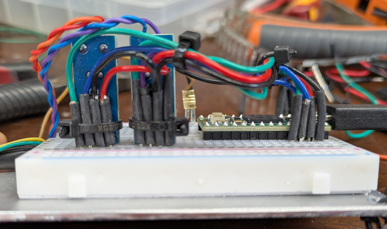
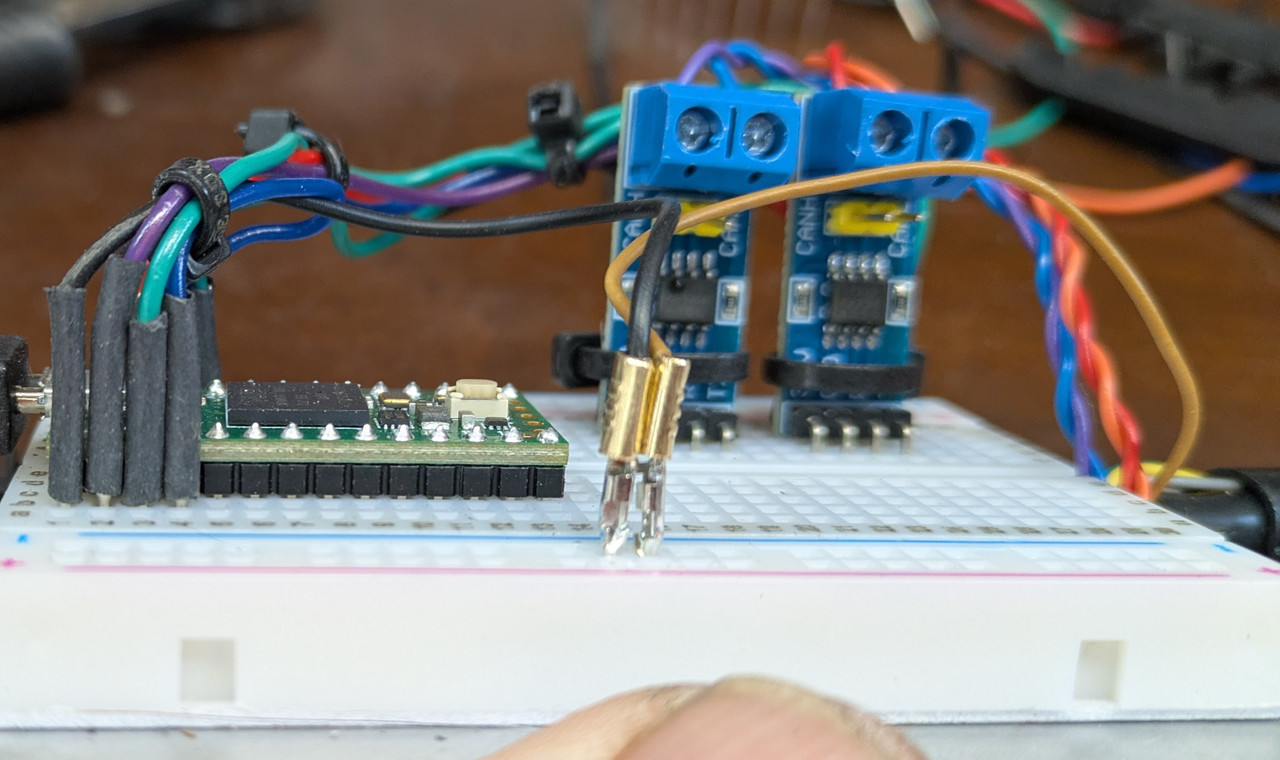
I did rework the wiring on the boards to simplify & used terminals slightly wider than the pre-made cables I had used
I will test this one. If it still doesn't communicate, I'll try switching out the CAN boards
-
vtl
- Posts: 4934
- Joined: 16 Aug 2012, 13:35
- Year and Model: 2005 XC70
- Location: Boston
- Has thanked: 130 times
- Been thanked: 686 times
Part with 103 on it is a resistor. 103 = 10 * 10^3 = 10000 Ohm. The other one is 121 = 12 * 10^1 = 120 Ohm.lookforjoe wrote: 17 Mar 2026, 20:01 Thank you for your help!
I thought those were diodes - sorry my mistake.
I didn't try running the car & loading the script - I assumed that would be a bad idea. I've only connected it with the key off.
I did rework the wiring on the boards to simplify & used terminals slightly wider than the pre-made cables I had used
I will test this one. If it still doesn't communicate, I'll try switching out the CAN boards
When the cracker puts car into programming mode, it clicks with relays and goes blank. No lights, no dashboard, no nothing. It feels like a battery was disconnected or "this sh*t from the internet broke my car!". Then you get a cracking progress displayed in your terminal.
Chinese counterfeit chips is unfortunately our reality. Some chips are dead on arrival, some can even communicate, but don't have linear latency, so timing attack fails.
-
lookforjoe
- Posts: 21
- Joined: 24 Jan 2013, 20:56
- Year and Model: 1991 743
- Location: NY, USA
- Has thanked: 2 times
- Been thanked: 4 times
Part with 103 on it is a resistor. 103 = 10 * 10^3 = 10000 Ohm. The other one is 121 = 12 * 10^1 = 120 Ohm.
When the cracker puts car into programming mode, it clicks with relays and goes blank. No lights, no dashboard, no nothing. It feels like a battery was disconnected or "this sh*t from the internet broke my car!". Then you get a cracking progress displayed in your terminal.
Chinese counterfeit chips is unfortunately our reality. Some chips are dead on arrival, some can even communicate, but don't have linear latency, so timing attack fails.
[/quote]

Thank you so much for noting that! I'll go through the other boards & see if I have any with 103 on the resistor. Otherwise, I'll go through my stash of surface mount resistors - it's been almost 20 years since I worked with them - it will be a challenge to see if my eyesight is up to it

-
- Similar Topics
- Replies
- Views
- Last post
-
- 1 Replies
- 9067 Views
-
Last post by RickHaleParker
-
- 6 Replies
- 8915 Views
-
Last post by abscate
-
- 27 Replies
- 27862 Views
-
Last post by cn90
-
- 10 Replies
- 10361 Views
-
Last post by jonesg
-
- 7 Replies
- 5535 Views
-
Last post by RickHaleParker