


Hi forum!
The problem started with the cables was broken at the hinge. "New" harness in place.
Brake led-lamp is tested and works when given 12v from external source.
The side brake lamps works.
I looked in vida and found that the high level stop lamp get its power direcly from the REM.
"When the stop lamp switch (3/9) is closed, a signal is transmitted to the central electronic module (CEM) (4/56). The signal is transmitted from the central electronic module (CEM) to the rear electronic module (REM) (4/58) via a directly connected cable. The high mounted stop lamp is supplied with power directly from the rear electronic module (REM). The stop lamp is supplied with power for as long as the stop lamp switch is closed."
What I found that doesn't work:
I have measured the voltage at pin 3 (red/yellow wire) in the connection between the REM and the rear harness and when I brake the voltage is only 0.13v.
So something is wrong with the REM? Any ideas?
2001 V70 High level stop lamp not working
-
mikealder
- Posts: 817
- Joined: 25 October 2009
- Year and Model: V70 2000
- Location: Blackpool
- Been thanked: 13 times
An earlier post of mine covering the brake lights with an explanation of how it works:
If you have a voltmeter set it to measure DC Volts (20V range is ideal) then connect the red meter lead to the + Terminal of the battery, connect the black meter lead to pin A4 on the plug that feeds the REM with the brake light signal then with the help of an assistant pressing the brake pedal check your meter reads 12V with the brake applied, the +12V signal from the foot pedal switch is turned in to a 0V/ open circuit by the CEM, the REM then uses this signal to switch on the relay for the outboard brake lights and turn on the driver circuit to illuminate the centre LED brake light - Mike
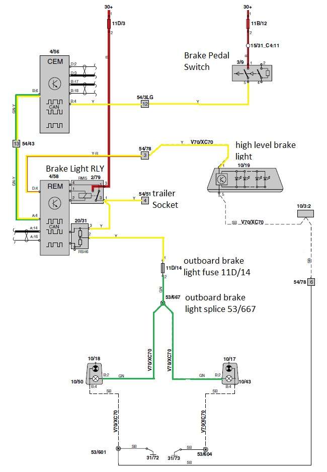
Some of the above troubleshooting was for a specific fault, in your case are you 100% sure the other wires going through the tailgate hinge point are intact?mikealder wrote:First the diagram which I have colour coded to make it easier to follow in the text below:
Lets start at top right with the fuse 11B/12 this feeds battery voltage to the brake pedal switch, with the pedal switch depressed the 12V travels through the yellow wire going through connector 54/3LG pin 12 before going to the CEM arriving on pin B4. The CEM then inverts this signal prior to feeding out a discrete signal to the REM on the green and yellow wire routing through connector 54/43 pin 13 which is under the left hand side of the rear seat base.
The REM now does two things with the 0V switched signal going in on A4, firstly it provides a +12V output on D4 which is a yellow and red wire this passes through the tailgate connector 54/78 pin 3 where it changes to a yellow wire routing to the center brake light. The other thing the REM does is to energise the brake light relay, can you hear/ feel the relays click when you (or a helper) presses the brake pedal).
+12V is fed through fuse 11D/3 which goes to the brake light relay, when this relay is energised it feeds power out on the yellow wires to the trailer socket 54/51 pin 4 and to the Shunt RSH6 which provides bulb failure detection for the brake light circuit, the yellow wire from the center of RSH6 feeds power to fuse 11D/14 (7,5 Amp rated). You should check that RSH6 Shunt is still fully connected to the REM or did it get disturbed when you popped the relays out or changing fuse?
The output of fuse 11D/14 is a green wire feeding power to splice 53/667 which is in the main wiring look under the REM, the splice is a small black heat-shrink covered metal barrel containing three green wires. The two green wires then connect to the brake light bulbs on both sides of the car.
Try fitting a new 7,5A fuse to 11D/14 then see if the brake lights work, if not take the REM off its mounting structure and have a good look at the rear of where the brake light relay is located, check the two yellow wires are still connected to the relay base and not damaged as in burnt out. - Hope this helps (My money is on the brake light relay starting to fail) consider swapping RMI4 (reverse light relay) with RMI5 (outboard brake light relay) and see if the fault moves to the reverse lights, if this is the case replace the relay - Mike
If you have a voltmeter set it to measure DC Volts (20V range is ideal) then connect the red meter lead to the + Terminal of the battery, connect the black meter lead to pin A4 on the plug that feeds the REM with the brake light signal then with the help of an assistant pressing the brake pedal check your meter reads 12V with the brake applied, the +12V signal from the foot pedal switch is turned in to a 0V/ open circuit by the CEM, the REM then uses this signal to switch on the relay for the outboard brake lights and turn on the driver circuit to illuminate the centre LED brake light - Mike
-
- Similar Topics
- Replies
- Views
- Last post