
Missed last week? Nooo! Undo that now: Tune a HPT or LPT. Wait, a LPT?. Take the Fast Friday Poll.
Turbos and Exhaust
Last week (Tune a HPT or LPT. Wait, a LPT?) we briefly discussed some of the basic differences between the Volvo LPT and HPT engines as well as some common upgrade paths. Thanks to some FF subscribers we had a request to dive in a bit deeper as it pertains to exhaust, turbo selection, and how it all relates to performance and drivability. So let’s dive in!
Turbo Terminology
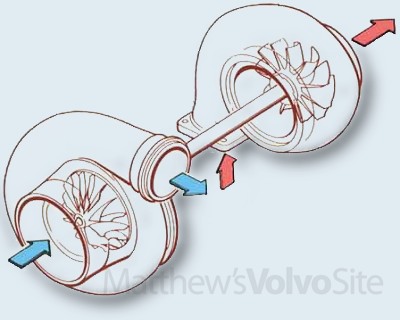
It’s important to understand the terminology in use as we discuss turbochargers so let’s define some basic terms. The compressor side of the turbo is where the air is drawn in, compressed and then fed to the engine intake manifold. The compressor side of the turbo is made from aluminum. The turbine side of the turbo is where the spent exhaust gasses from the combustion process are pushed past the turbine wheel and in turn exit via the downpipe through the exhaust. The turbine side of the turbo is made from cast iron.
For most Volvo turbocharged models the Mitsubishi TD04 family of turbochargers are used however there are some exceptions, for instance the R models from 2004-2007 and the S60T5 past 2005, but for now let’s focus on the more frequently used TD04 family of turbos. These turbos are commonly referred to by their numeral designation and as you might suspect the larger the number the larger the turbo in terms of the horsepower it can develop. These turbos are known as the 13G, 14T, 15G, 16T, 18T ,19T. One interesting fact to note is that while the compressor side of the turbo gets larger (in terms of flow) the turbine side of the turbo stays the same. The turbine housings do change some from conical flange, to straight flange, to angle flange but the overall flow on the turbine side is most limited by the turbine wheel which is the same throughout the TD04 family.
Flow: Get The Exhaust Out!
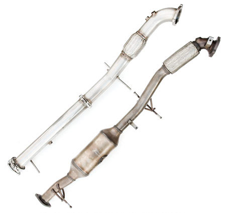
As it relates to exhaust the most considerable impact to exhaust gas flow (aside from the turbine side of the turbo) is the catalytic convertor that is located in the downpipe. The purpose of the catalytic convertor is to reduce undesirable tailpipe emissions. The factory catalytic convertor is a pretty nicely flowing unit but as you start to exceed the 250bhp level of power this becomes a significantly restricting factor in flow in the exhaust. This is why downpipe upgrades with higher flowing catalytic convertors become so popular when tuning these cars.
Back pressure is most undesirable as it slows the ability of the exhaust gasses exiting the combustion chamber to push past the turbine wheel and create boost pressure.
It’s not uncommon at all for folks to upgrade their downpipe to achieve greater flow while leaving the remainder of the exhaust in stock form to keep tailpipe volume more reasonable. Stock resonators and mufflers do impede flow at higher horsepower levels but not nearly as much as the catalytic convertor in the stock downpipe . This is in part due to the exhaust gasses cooling considerably by the time they reach the resonator and muffler such that the gasses are more dense, take up less space, and therefore create less back pressure as they exit the tailpipe.
All in Moderation
I mentioned last week a fellow enthusiast that I work with who has a LPT engine with a larger 19T turbo installed to it. And while at first blush this might sound like quite a bit of fun there is risk to the engine with this large of a turbo installed. The risk comes from too much boost too soon in the RPM range . The amount of force imparted to the rods is only part of the issue, the other side is heat transient and ring expansion. We'll cover that in a moment, but first let’s understand why the larger turbos in the TD04 family can be prone to boost spike or rapid early RPM boost development.
The 19T turbo uses the same size exhaust turbine as the considerably smaller 13T, however the 19T compressor side is quite large and can consequently support considerably more power. This ‘imbalance’ in flow from the compressor side to the turbine side creates an imbalanced inertia. Inertia is not quite the proper term for this but it gives us a simple way to view how and why this imbalance creates boost jumpiness.
Larger Turbos Take Longer to Spool
Let’s consider what the turbo is experiencing from the turbine wheel to the compressor wheel as this example scenario is played out. As the engine revs, exhaust gasses are pushed out the exhaust port on the cylinder head and begin to exert force against the turbine wheel. With the smaller 13T turbo the amount of force necessary to start to develop the first pound of boost (boost threshold) is achieved earlier in the RPM band. However the 19T’s larger compressor wheel requires more force and flow to develop that same first pound of boost pressure so higher exhaust backpressure between the exhaust valve and the turbine wheel develops. As the exhaust pressure rises it reaches a point where the compressor ‘inertia’ is overcome and the turbo starts to spool very quickly. This quick spooling is then propagated even more as the compressor side feeds more pressure to the combustion chamber which results in more pressure out of the exhaust port after combustion, the cycle becomes self-energizing over just a few seconds and can in certain circumstances over boost the engine.
Heat Transient: The Upward Spiral
This over boosting is most troublesome not only from the force it puts on the connecting rods early in the RPM range but also from the heat transient (heat created over time) that occurs in the combustion chamber. This overly quick spooling creates rapid increases in compressor outlet temperature which the intercooler can’t adequately cool over such a short period of time. This added temperature is then transferred into the combustion chamber and the resultant heat is imparted to the piston and rings. If this occurs long enough and fast enough the piston rings can overheat and expand such that they bind in the combustion chamber (Ring pinch) . This puts added strain on the rods as the crankshaft tries to force the piston up the bore for the exhaust stroke.
Fueling is Cooling
To combat the quick rise in temps that can occur in these situations we frequently add fuel to the mix, this is why in higher boost It’s desirable to be richer than at part throttle or cruise. In the tuning world we call this “Lambda Protection”. Another method to help combat ring pinch is to increase the ring end gap. This is most conveniently done while in the process of rebuilding an engine so for those who may be in the midst of such a project, you might want to consider that as a way to help keep your rods safe!
Robert Lucky Arnold
~ ~ ~
[list][*]Questions, comments, arguments and freakouts accepted and encouraged. Really. Lucky WANTS to answer your questions.
[*]If you want to remain anonymous, email me your question or comment and I will post it as "Anonymous User".
[*]It takes Lucky and me several hours combined to bring you Fast Fridays. Your questions and comments validate FF's value.
[*]I write paragraph headlines, and sometimes article headlines. Yell at me if you find these not to your taste.
[*]Same thing with italics and bolds , they're all mine.
[*]Science + cars, whoo![/list]
Matt