1. Breadboard: An experimental model, especially of an electric circuit; a prototype.
Etymology Breadboard ( electronics ): The original electronics breadboards where literally a board to slice bread on with nails as terminals and copper wires as pathways.
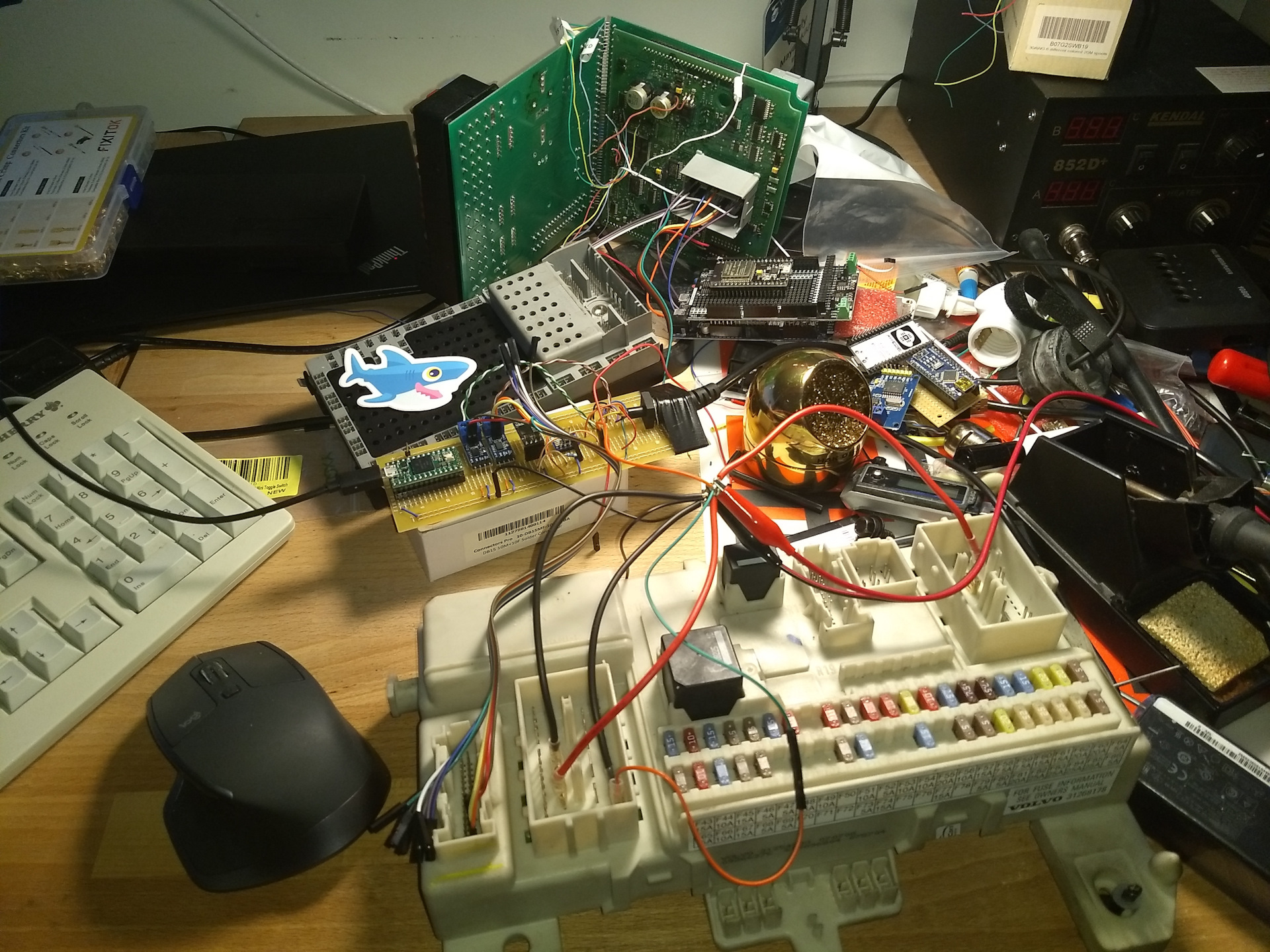
2. Yours is soldered breadboard. Two steps up from solderless breadboard. The other is wire wrap breadboard.
3. What are you using for the power source? Insignificant power could be a problem.
4. Use some CAN twisted pairs between the CAN transceivers and the OBD2 connector. A twisted pair reduces electromagnetic radiation from the pair and crosstalk between neighboring pairs and improves rejection of external electromagnetic interference. In other words a twisted pair is quite compared to a untwisted pair. The wire size and twist rate needs to be balanced for optimal performance. Go get some CAN twisted pairs out of a junk car and be done with it. ( The Orange - Orange/White and Gray - Gray/White in my picture. )
5. Shorting the wires between the MCU and CAN transceivers may help. They are laying on top of each other and maybe picking up too much crosstalk. You can run some of the wires on the underside of the board and reduce the size of the hornets' nest.
If Twisted pairs and cleaning up the hornets' nest. is not a cure. Move on to the CAN transceivers.
7. Problems have been reported with the 3.3V Chinese knock off chips. If it where mine I would switch to some good 5V CAN transceivers. You tried everything else, might as well exhaust the last remaining hardware possibility.