


I created an account just to thank you!
Help with powering S60 seat -- Not in a Car Topic is solved
Hey did you figure this one out, I’ve got the same style board, like everyone else I just want to power the seats and bypass the canbus, being fitted in a vanbornhall wrote: ↑10 Aug 2022, 06:38Right, I'm going to quote myself really quickbornhall wrote: ↑10 Aug 2022, 06:33As far as I can tell, this board seems to reverse polarity where pin 6 on the black connector is the common "ground" (for lack of a better word) or M– for the motors, and pins 2-5 is M+ for each motor (Fwd/Rev, Back, Up/Down, Length). Pin 1 is 12V and Pin 7 is GND.
I believe the board takes care of this "logic", so that no two switches can be active at the same time. Seeing as the motors all seem to share one common power line (whether it is – or + polarity), reason says that trying to run one motor one way while running another the "other" way would cause a short...
Basically, I don't think it is possible to "daisy-chain" this board as was done on others earlier in this thread.
-
Shopper0080
- Posts: 1
- Joined: 19 September 2024
- Year and Model: 2004 v70
- Location: Finland
Here's a wiring diagram for Volvo V70 P2 driver's seat. I guess it works for other seats also with same connectors.

A1 & B1 -> +12V
A2 & B4 -> Ground
The power seat has three basic programs:
1.) Door open, key in off position: 10 minutes of adjustment
2.) Door Closed, key in off position, 30 seconds of adjustment
3.) Door Closed, Key in ON position, always allow adjustment
Program #2 is activated when wiring the seat this way. If anyone knows how to bypass the adjustment period please share.
-
lookforjoe
- Posts: 12
- Joined: 24 January 2013
- Year and Model: 1991 743
- Location: NY, USA
- Has thanked: 1 time
- Been thanked: 3 times
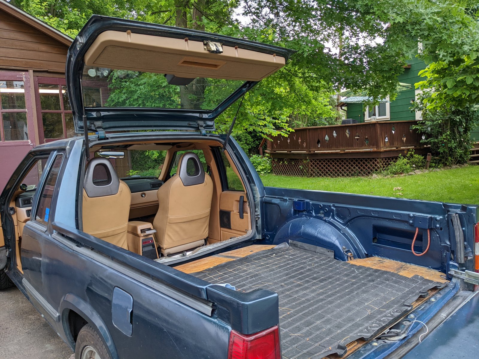
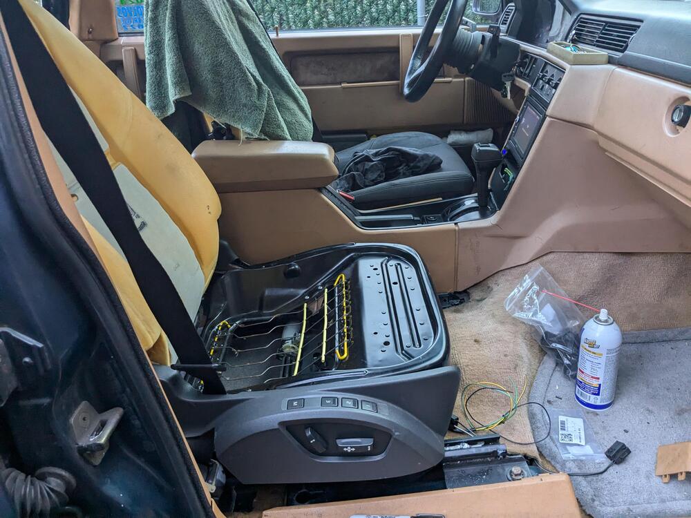
Like Bornhall, I am using 2012 C30 (P1) power/memory seats in a non-factory install (1991 Volvo 743)

I had previously modded Honda S2000 seats to fit the 740 seat tracks, however they are just not as comfortable or as adjustable as the C30 seats.
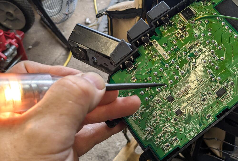
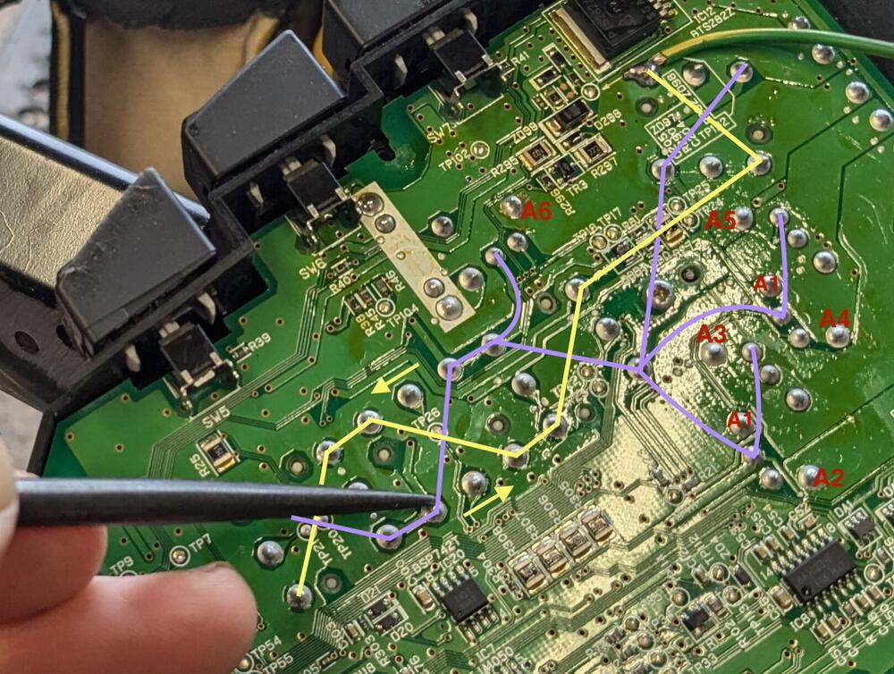
The circuit board, while similar to earlier ones posted, has no direct connection from the main feed A1 (30) or ground A7 (31) to the switch grid (indicated in yellow & purple). This is what I have found so far, metering out the connections. A2-A5 are the motor I/O. There are 3 relays, one for the ground circuit & 2 to switch output for the seat motors.


Relay schematics, based on the NEC part numbers


I going to hope that bypassing the entire CAN circuitry by switching the grounding relay coil (RL3) will activate the switches. Not concerned with any of the extra niceties, just basic switch operation. I'll find out later today.
I had previously modded Honda S2000 seats to fit the 740 seat tracks, however they are just not as comfortable or as adjustable as the C30 seats.
The circuit board, while similar to earlier ones posted, has no direct connection from the main feed A1 (30) or ground A7 (31) to the switch grid (indicated in yellow & purple). This is what I have found so far, metering out the connections. A2-A5 are the motor I/O. There are 3 relays, one for the ground circuit & 2 to switch output for the seat motors.
Relay schematics, based on the NEC part numbers
I going to hope that bypassing the entire CAN circuitry by switching the grounding relay coil (RL3) will activate the switches. Not concerned with any of the extra niceties, just basic switch operation. I'll find out later today.
-
lookforjoe
- Posts: 12
- Joined: 24 January 2013
- Year and Model: 1991 743
- Location: NY, USA
- Has thanked: 1 time
- Been thanked: 3 times
So, working on the switch today - I had it hooked up to the seat & powered. I figured out that the switch power & ground circuit is activated by the switched power on the secondary connector (B1) . Using a test light, I confirmed the (+) switching action (purple tracer). I tried activating the relay(s), nothing. I tried bridging the A6 terminal to the ground run of the switches (yellow tracer). I tried jumping the ground relay (3) and one leg of relay 1 or 2, and none of that activated the output to any of the 4 motors.
I considered hooking up one of the older power seat switches I have from >MY2000 P80 & 7/960s. Problem with those is that the motors are each powered by 2 separate wires from the switch module - the newer motors share the ground leg at the switch module. I would have to rewire the ground legs of each motor to isolate them from each other. I went back to playing with the stock module.

At some point in testing permutations, I bridged a circuit on the board that created a short - I heard the pop that let the smoke out of something on the board. After that, three of the 4 switches operate without issue. The fore/aft one does not. I wish I knew which chip I fried, I would do the same for the passenger switch. I'm going to try bridging the switch 4 contacts to A2 & A6, to see if that overrides the circuit that is inhibiting operation.
B2 & B5 connect to the seatback release switch - allows you to move the seat forward when the setback is flipped forward. That works.

I bridged what was formerly the heated seat switch supply, to provide power to the seat modules

This was the seat end - I replaced the terminals/connector with terminals that can handle 25A

I considered hooking up one of the older power seat switches I have from >MY2000 P80 & 7/960s. Problem with those is that the motors are each powered by 2 separate wires from the switch module - the newer motors share the ground leg at the switch module. I would have to rewire the ground legs of each motor to isolate them from each other. I went back to playing with the stock module.
At some point in testing permutations, I bridged a circuit on the board that created a short - I heard the pop that let the smoke out of something on the board. After that, three of the 4 switches operate without issue. The fore/aft one does not. I wish I knew which chip I fried, I would do the same for the passenger switch. I'm going to try bridging the switch 4 contacts to A2 & A6, to see if that overrides the circuit that is inhibiting operation.
B2 & B5 connect to the seatback release switch - allows you to move the seat forward when the setback is flipped forward. That works.
I bridged what was formerly the heated seat switch supply, to provide power to the seat modules
This was the seat end - I replaced the terminals/connector with terminals that can handle 25A
-
lookforjoe
- Posts: 12
- Joined: 24 January 2013
- Year and Model: 1991 743
- Location: NY, USA
- Has thanked: 1 time
- Been thanked: 3 times
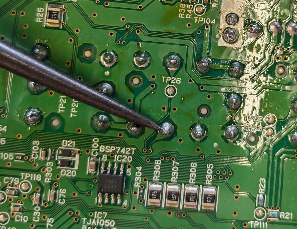
Wrapped this up (finally). I tried a number of ways to connect the center pins of SW4 to the fore/aft motor (A2), without much success. I found that spiking the center pin to the adjacent power pin would bring the circuit alive - but only long enough to move the motor briefly. I repeatedly spiked the connection, to see how long I could get it to hold function. Doing this ultimately killed whatever switches the power to the switch grid, which turned out to be what was needed, as with that I added a jumper from the switched power feed at the top of the card to the switch power grid & now all the switches work. I guess I basically lobotomized the board 


-
lookforjoe
- Posts: 12
- Joined: 24 January 2013
- Year and Model: 1991 743
- Location: NY, USA
- Has thanked: 1 time
- Been thanked: 3 times
Passenger seat module. Grid is reverse of driver's module
I cut to the chase & momentarily shorted the grid. Switch module then operated as one would hope, without the need for the CAN signal.
I cut to the chase & momentarily shorted the grid. Switch module then operated as one would hope, without the need for the CAN signal.
-
- Similar Topics
- Replies
- Views
- Last post
-
- 2 Replies
- 1812 Views
-
Last post by Oleelstad
-
- 1 Replies
- 1738 Views
-
Last post by darylrobert