MVS Contributor Jason Reed slays the tie rod dragon with one swing of the DIY sword.
jreed » Inner and Outer Tie Rod End Replacement
Introduction
This DIY guide shows how I replaced the TRW inner and outer tie rods on a 1997 Volvo 855 GLT with 165k miles. I benefited greatly from the write up by Nlemerise who did the job on his V70. His guide was posted on Swedespeed:
http://forums.swedespeed.com/showthread … e-Rod-Ends
The link to his PDF appears dead, but luckily it’s also in the MVS database here:
https://www.matthewsvolvosite.com/forums … =1&t=11806
Ozark Lee has also written up a procedure for the outer tie rod ends here:
https://www.matthewsvolvosite.com/forums … =1&t=52270
I took pictures at each step of the procedure, so it was easier to put them into a PDF than upload each one of them one-by-one. The full write up is here:![]() Inner & Outer Tie Rod End replacement Volvo 850 TRW rack by Jason Reed.pdfFully illustrated PDF version(6.57 MiB)
Inner & Outer Tie Rod End replacement Volvo 850 TRW rack by Jason Reed.pdfFully illustrated PDF version(6.57 MiB)
How I knew I needed to do this job
The bellows on the outer tie rod end on the driver’s side was split. Grease was leaking out. It would not be long before this joint would be dry and corroded. Then it would loosen up and start squeaking.
The tie rod ends on the car were OEM (TRW arms with steering boots labeled TRW / Volvo). Check if your rack is SMI or TRW – this write-up is for the TRW rack – the SMI may be different.
I think these parts were original to the car – this is the first time I’ve replaced them. The original owner sold me the car at 64k miles but I don’t know if she ever had them replaced or not.
At the end of the job after removing the tie rod end and inspecting the damaged boot on the driver’s side:
The rubber on the passenger’s side boot was deeply cracked though not yet split. I decided it made sense to replace the outer tie rods on both sides at the same time since you have to get an alignment after changing tie rods and the passenger’s side boot was sure to split and need changing soon.
As for the inner tie rods, I originally wasn’t sure if I should go to the expense of changing them at the same time. To try to gauge their condition, I jacked up the front end and tried feeling the inner joint inside the steering boot for looseness while my wife turned the steering wheel. I also tried pulling on the wheel at the 3 and 9 o’clock positions while feeling the inner joint to see if I could feel looseness, but I couldn’t detect much.
I decided that the cost of the inner tie rods and steering boots was not so high that I would risk having to get into the steering system again later. This kind of decision is always a tricky balancing act between “pay more now or maybe pay more later” and it’s not easy to come up with a hard and fast rule on the decision. Because this job requires an alignment, in the end I decided to go for new inner and outer tie rods, plus steering boots, and just do the whole job the first time.
Procedure Overview
A) Remove outer tie rod end balljoint from steering arm
B) Remove steering boot from inner tie rod end
C) Remove inner tie rod end from steering rack
D) Install new inner tie rod end
E) Install new steering boot
F) Install new outer tie rod end and set the proper length (more on the length adjustment below)
G) Do A-F on the other side of the car
H) Get the car aligned
Time
About 4 hours including jacking up the car, stopping to take photos, and cleaning up and putting away the tools afterwards.
Tools
- Wire clippers
- Knife
- 18mm six point socket and ratchet wrench
- Torque wrench
- Small bent tip pliers
- 2 adjustable pliers (10” and 12” lengths worked well for me)
- 2 adjustable wrenches or the proper (18mm?) metric open end wrenches
- Vice-grips or other locking pliers
- 2 Tie wraps
- Striking hammer and a ball peen hammer for loosening the tie rod balljoint
Materials
Silicone grease
Loctite blue (medium strength) Type 242
Brake cleaning spray to remove grease and oil
Parts
I got all the parts from Darryl Waltrip Volvo.
New steering boot kit, part 271601. Note: two needed, one for each side. The boot kit includes new clamps, a new inner tie rod end lock nut and a new outer tie rod end balljoint nut. Note: if you buy the new outer tie rod ends, you will get a balljoint nut with those too.
You also get a new black rubber band which goes around the steering rack end.
For the clamps, I opted to use the new small blue spring clamp that came with the kit, but I opted to use nylon tie wraps instead of the metal screw clamps at the rack-end of the inner tie rod because tie wraps are a bit easier to install. Note also that the original clamps were not metal – they were plastic and similar to tie wraps.
Outer tie rod end. This part is side-specific. Part 271598 for the left (driver) and 271599 for the right (passenger) side. The outer tie rod ends are stamped TRW on top, made in Germany.
Inner tie rod ends, part 3546266. (Two needed, same part for left and right sides). These came with “NO ROST” rust preventative paper wrapped around the shafts and had balljoints that were pre-greased.
Other instructions / repair information:
VADIS instructions were as usual rudimentary. It’s always worth checking to get part diagrams and numbers and see if there might be helpful information, but in general the level of detail is minimal. I picked up a few helpful tips, among them:
1) Counterhold the steering rack when loosening the inner tie rod end so that the rack can’t twist and be damaged.
2) VADIS had a picture of the black rubber band that goes around the steering rack. The new boot slides over this band.
3) Torque the outer tie rod end balljoint nut to 52 ft-lbs.
Here is an example page from VADIS: (see PDF file)
The VADIS guide also specifies that the boots be filled with 20g of special Volvo grease. My new Volvo boot kits didn’t include the grease, so I didn’t put any in the boots.
I also have the Chilton Volvo 1990-98 and the Haynes 850 1993-97 manuals. The Chilton manual had more detail (14 steps for the outers with torque specs of 52 ft-lbs for the locknut and balljoint nut, 16 steps for the inners) and 6 photos of the outer tie rod ends. This is much more detail than the Haynes, which is not often the case – it is handy to have both manuals for reference.
Detailed sequence
Step 1:
Slightly loosen wheel lug nuts. Chock rear wheels. Jack up front of car. Place jack stands. Remove wheels. Inspect tie rods. I applied penetrating oil to the locknut and balljoints and let it soak overnight.
In the photo below you can see some deep cracking in the rubber bellows at the ball joint on outer tie rod. This tie rod end was on the passenger’s side.
The photo below shows the inner tie rod end covered with the bellows. A metal clamp at the small end and plastic clamp at the back end near the rack hold the boot in place.
Step 2: Loosen 18mm nut on ball joint. I used a 6 pt deep ½” drive socket.
Once the nut it loose, remove it if you are not going to reuse the outer tie rod. If you are going to use it again, then I would leave the nut on to cover the exposed threads during the next step when you whack the steering arm with a hammer to make the tapered part of the ball joint pop out.
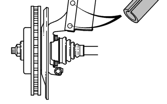
Step 3: Strike steering arm.
I tried whacking the steering arm with a flat faced hammer (shown above) but after about a dozen whacks there was no movement of the tapered balljoint. I decided that more blows and heavier blows were needed, but I was concerned that I might hit the brake shield or brake rotor and cause unintended damage.
So I used two hammers, one ball peen hammer placed on the steering arm and a second hammer to strike the back of ball peen and transfer the blow. This was a tip I picked up from watching a video called “Steering Concerns” by Dan Reed (no relation) from the Community College of Philadelphia in which he replaces inner and outer tie rod ends on another type of car. I watched this video a couple of times—it’s great!
http://www.ccp.edu/site/about/ccptv/car … cerns.html
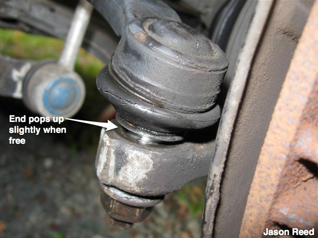
When it pops loose, you will see a gap.
Withdraw tie rod end from steering arm.
Next, you turn to the boot covering the inner tie rod. Clip the plastic clamp at the back of the bellows. These clamps are similar to tie wraps but seemed to be designed to lock at the correct position rather than be adjustable.
Be prepared for ATF to pour out of boot (if the steering rack seals are weak or failing). Put a catch pan underneath just in case. I was a little surprised to see how much ATF had leaked into the boot, especially on the passenger’s side. The driver’s side had less fluid, but there was some. I may have to have the rack rebuilt or the seals replaced at some point.
Remove clamp on front of boot.
Next, slice the boot (don’t do this if you’re not going to replace the boots with new ones – you can disassemble the old inner & out tie rods and re-use the boot if you want). I decided to speed the repair up a bit by slicing off the boot to get it out of the way without having to unscrew the outer tie rod end from the inner tie rod end.
View of exposed inner and out tie rods, ready for inner tie rod end disconnection.
Picture of useful pliers for removing inner tie rod end:
eally like this set of pliers pictured above that I got at Harbor Freight. I only needed the 10” and 12” sizes to remove and install the inner tie rod ends, but it’s great to have the 16-inch “commander” (at the far right) available in case it’s needed. You could use other tools such as a pipe wrench or perhaps a special inner tie rod end removal tool if your inner tie rod end has flats to grip, but these 10” and 12” pliers were all I needed. They worked well for me.
To loosen the inner tie rod, counterhold the very end of the steering rack (not the shiny machined surface of the main steering shaft) with one plier (the 10” worked well for this) while twisting the inner tie rod end off with the 12” plier.
Once you break the threads loose on the inner tie rod end, you may be able to spin it off all the way by hand. On the passenger’s side it was a bit sticky and I had to use the 12” pliers a time or two to fully unscrew it. I kept the 10” pliers in place to keep the rack from twisting.
After I removed the inner tie rod end, I could see the divot that had been applied at the factory to lock the tie rod end to the rack – this divoting process is described in VADIS. I opted to use Loctite blue 242 threadlocking compound instead of trying to divot the new inner tie rod end.
I checked out the original tie rod ends for excessive play or looseness but found very little. The original parts were almost as tight as the new parts – not as stiff as the new joints but still resistant to movement, yet smooth once the resistance was overcome. If it hadn’t been for the split boot, I don’t think I would have needed to replace the tie rods. This was a little surprising because I was expecting to see some looseness just based on the age and mileage (17 years and about 165k miles).
Next, remove the old black rubber band on the end of the steering rack if your boot kit comes with a new one (the OEM boot kit includes it). Otherwise, leave the old one on.
Then, clean up the threads on the inside of the steering rack arm with some brake cleaning spray. This is to make sure the new inner tie rod end will tighten and seat well and so that the thread locking compound will bond and hold.
Next, I compared the old parts with the new to make sure that I had the right stuff. The new parts had the same shape and size as the originals.
To begin the installation of the new parts, first I stretched the new black rubber band over the rack. I put a little silicone grease on it first and then rolled it over the edge and onto the mating surface.
Then I cleaned the threads of the new inner tie rod end with brake cleaner in case they had oil or a protective film on them that might prevent a good bond with the Loctite.
Then I applied one drop of the blue Loctite 242 to the threads.
Next I threaded the new inner tie rod end into the threads on the rack.
To tighten, I again used the counterhold method with the 10” and 12” pliers. I tightened it up “tight” but not too tight. There’s no easy way to get a torque wrench into position here – I just went by feel.
Next it is time to install the new boot over the inner tie rod end. Remove the rust-preventative paper and the yellow plastic cap if you haven’t already. I applied a little silicone grease to the mating lip inside the end of the boot. Partly this was because I had studied Nlemerise’s write-up of how difficult it had been to install the boot and I wanted to make it easier to slide it over the rack. In the end, the boot installed easily and quickly with no problems. When I re-examined Nlemerise’s write-up afterwards, I realized that the boot used was probably not OEM – it looked shorter and had fewer pleats than the OEM part. I think this is why he reported having so much trouble getting the new boot onto the end of the rack. So, I’d recommend getting the OEM boot kit to help make the job go smooth and easy.
With the boot in position on the rack, slide the front of the boot over the smooth machined surface on the inner tie rod end as shown:
Then, I used bent tip pliers to open and slide the blue metal spring clamp over the front of the boot.
Next I installed the tie wrap around the boot at the rack end and clipped off the excess.
Next, turn the lock nut onto the inner tie rod end. Spin it almost all the way up towards the rack end, stopping about 6 turns short – the exact number of turns will depend on what you had on your original parts, as described below.
Transferring the dimensions from old to new:
At the beginning of this project I was considering what was the ‘best’ way to keep the lengths of the new rods about the same as the old rods so that the alignment of the wheels wouldn’t be too far off during the trip to the repair shop for realignment. There are several methods that people use, including these (there may be more):
1) Measure the lengths of the originals and set the new ones to the same length.
2) Unscrew the outer tie rod end and count the turns until it is off, so that the new outer tie rod end can be screwed the same number of threads onto the new inner tie rod end.
3) Count the number of exposed threads on the original inner tie rod end and screw in the new outer tie rod end to match the number of exposed threads.
Of these methods I decided that in my situation #3 was the easiest. For method #1, it seemed difficult to make a precise measurement from the rack to the outer tie rod balljoint. For #2, I would have to remove the original outer tie rod end from the inner tie rod end in order to count the turns – this seemed like extra work since the parts were worn out and not going to be re-used. If you are re-using either the inner or outer tie rods, you may want to use method #2.
Following method #3, I set the new locknut to have the same number of exposed threads as on the original tie rod end, as shown below.
Then, thread the new outer tie rod end onto the inner tie rod end until you reach the lock nut. Don’t allow the locknut to turn.
Next, I used a couple of adjustable wrenches. The bigger one is to hold the lock nut in place – don’t turn it because it is controlling the length of the tie rod assembly. The smaller one in the front is used to hold the flats on the outer tie rod end and tighten it up against the lock nut. Don’t worry that the ball joint on the outer tie rod end is not pointing in the right direction at this stage to fit back into the steering arm – you will rotate the whole tie rod end in the next step to aim it.
Then, remove the white plastic protective cap if you haven’t already.
Insert the balljoint into the steering arm and begin tightening the nut.
You may find that the balljoint will tend to spin while you try to tighten the nut. I used a pair of vise grip pliers to hold the shaft of the balljoint:
Volvo recommends 70 N-m / 52 ft-lbs torque for tightening the tie rod nut.
Once the balljoint has settled into its taper in the steering arm, it won’t spin as you apply the final tightening torque.
You’re done here. After you do the first side, it will be easier to do the second side.All done on this side
After I got the car back together with the wheels on and lug nuts torqued to 81 ft-lbs, my wife drove it to the alignment shop the next day. She reported that going over to the shop it drove fine with no obvious pulling or drifting, so I guess the thread-counting method was good enough.
After the alignment, the car steers fine and all seems to be well. The steering seems slightly tighter than before but this is subjective.
As mentioned at the top of the post, I took pictures at each step of the procedure, so it was easier to put them into a PDF than upload each one of them one-by-one. The full write up is available for download here:![]() Inner & Outer Tie Rod End replacement Volvo 850 TRW rack by Jason Reed.pdf Fully illustrated PDF version(6.57 MiB)
Inner & Outer Tie Rod End replacement Volvo 850 TRW rack by Jason Reed.pdf Fully illustrated PDF version(6.57 MiB)
Good luck and enjoy the job!
Volvo 850 DIY Inner and Outer Tie Rod End Replacement w/50 Photos!
Welcome to Matthews Volvo Site! Your one stop shop for all Volvo news, help and DIY fixes. We feature the Volvo Repair Database, the best Volvo Forum, and an awesome monthly Volvo newsletter. Joining is always free!
Subscribe to the MVS Newsletter
The MVS Volvo Newsletter is a once-a-month email delivered to your email. It’s simple to unsubscribe at any time if you change your mind.
Visit The Official Volvo Cars Website
Last Updated on August 19, 2022