MVS Volvo Forums moderator and all-round gentleman Ozark Lee explains with great detail how to fix your 850’s (or up-to-year-2000 XC-70, S70 and V70) dash once and for all. This repair fixes broken dash mounts, which cause sagging, vibration, squeaks and rattles.
Ozark Lee » My dashboard mount saga began about 5 years before this post with the purchase of a 1996 850 Platinum Edition turbo. When I purchased the car the right hand side of the dash was literally flopping around when going over bumps and all of the movement resulted in a lot of noise. I pulled the dashboard and the initial repair was documented in this thread:
Volvo 850 Dashboard Mount Repair.
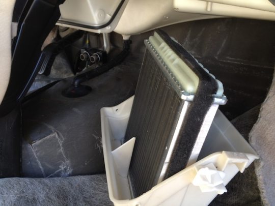
Fast forward 5 years and the evaporator decided to give up the ghost. Following the same procedure as before, I removed the dash and set forth to replace the evaporator and restore the air conditioning in the car. Over the 5 years and 75,000 miles the dash had started to get noisier and it would squeak badly if the car was left out in the sun or if the defroster was run on a high temperature in the winter.
Upon removing the dash I got a chance to evaluate the earlier repairs and effect further repairs.
The initial repairs from 5 years ago did work to an extent but they didn’t completely remedy the problem. The mounts that were not broken before remained largely unbroken. They tried to break but the reinforcing limited the damage to cracks around the mounts rather than the mount breaking free from the duct.
The previously broken mounts, however, detached again and this time they took more of the defrost duct with them. That said, enough of the reinforcing metal remained affixed to the duct to hold the dashboard in place.
The flaw in the initial reinforcing plan was not the reinforcing strap itself but rather what the strap screwed into as well as the concentration of force on those mounting screws which occupy a small surface area.
Dashboard Mount Repair – Version 2.0
When a dashboard is this damaged the first choice is to try to locate a salvage dash that is in good condition but that is easier said than done. Unless you happen upon a good one at a pick and pull they can also get very expensive.
My local pick and pull had an 850 but the dash was nearly as broken as what I have and it lacked the burl wood trim.
The thought process for Version 2.0 was to provide a more substantial mounting surface for the reinforcing and to further create more substantial mounts that can effective reduce or even eliminate the load on the factory mounts.
A trip to Lowes to get ideas led me to the sheet metal section where I looked at sheet aluminum. Lowes turned out to be a real bad idea since they seem to think an 8” x 16” sheet of 0.025 aluminum is worth $40.00. I just laughed and went down the street to the local, “if they don’t have it, you don’t need it” hardware store. There I bought the same sheet for $8.00 and, while I was there I also looked at steel to fabricate the mounts. The more I looked at things the more I started to think about step flashing. A stop at the roofing department led me to 5” x 7” steel and aluminum flashing so I bought a few pieces of each to experiment with. They cost around 60 cents each so experimenting was cheap.
The aluminum was a thinner gauge, measuring 0.015 thick and the steel was 0.010 thick. While at the hardware store I also picked up a tube of the syringe style JB Weld 6 minute epoxy and some JB weld marine water weld. At the end of this process I used 4 tubes of the syringe style liquid epoxy.
Once I got home and moved the dash to an appropriate large flat surface that is well lit (the dining room table) and I began to try to form the thicker aluminum around the defroster duct. I found that it would be very difficult to get the 0.025″ aluminum to take shape without somehow pre-forming it. This is where someone with an English Wheel and auto body experience would excel. Me, I really suck at bodywork unless it is as simple as bolting on a new fender or a door that is correctly painted to begin with. I found that the 0.015” thick aluminum was much easier to deal with and I could get it to easily take shape around the contour of the duct. I didn’t get too carried away bending the thicker aluminum and I was able to return it for a refund.
As the dash came out I found that all of the attachment points for the other panels were in the process of disintegrating. The lower mounts along the A pillar, the lower dash panel mounts, and the glove box door mounts were all bad. The glove box mounts were also bad but the glove box itself had broken at the screw mounts after the first time I had it out and I didn’t spend any time or resources on the glove box. It seems to wedge itself into position and stay there. For day one, after gathering materials I started to repair all of the other mounts.
The lower plastic mounts at the A pillar don’t structurally do much except hold the lower trim around the door sill in place. The lower part of the dash is reinforced with steel behind the mounting screw which carries the load of the dash. That said, I just filled in the crumbling plastic part with the JB weld epoxy mix so as to secure the door sill trim back in place. On the badly damaged, as in not much in the way of plastic even remained, lower dash panel mounts I used the JB Weld marine putty. It is very easy to work with. To activate it you cut a piece off and knead it until it turns a uniform light gray color and then you have about 5 minutes to form it around what you want to repair before it starts to harden. It is stiff enough that you can mold it into any shape and it will keep that shape. For the mounts that still had enough plastic to work with I used the more liquid 2 part epoxy. Here are some pictures of the repaired panel mounts.
Getting back to the main dashboard mounts I used one of the broken pieces to roughly size a new support. I figured that the new support would need to structurally take the place of the existing mounts so it would need to be reinforced on the sides.
Here is what I came up with.
The breaks on the side supports need to mirror each other. One will fold to the left and the other to the right.
Once the bracket pieces are fabricated they need to be joined. For this I used a small tip on an Oxy /Acetylene torch and silver solder which I had on hand. I use it for soldering ground systems together on radio and TV stations. Soft solder will not be strong enough for this application.
The steel flashing has a zinc plating and the solder doesn’t flow well at the joints in its presence. I knocked the plating off with a grinder to get to bare steel so as to provide a good surface for the solder adhesion.
I used welding vice grips hold the parts together for soldering. I will not win any prizes for soldering prettiness but they are plenty strong. The solder joints were made on the inside of the mounts. The heat is much different between soldering copper (which I am used to) and steel (which I don’t work with often). The brackets represented a learning experience and they got easier as I adjusted the torch until I was happy with the way the silver solder flowed. I used the silver solder since I had it on hand, brazing rod would be equally as acceptable.
Depending on the condition of the outboard mounts you may need to leave the outer side of the bracket off. As shipped, the outermost OEM mount sides have a fin for additional strength and to also establish a vertical position for the dash. With the fins the additional side support on the new brackets will not fit over the original bracket. One of my side brackets was good but on the other side it was gone. To a large extent, each mount will wind up fitting differently over the original. For the good mount I soldered straps onto the new mounts so as to anchor the outboard side of the new mount to the new surface.
I then used the most substantial broken mount to test fit the bracket. The top of the OEM mount is flat and going into the corner may have left more excess bracket height than the firewall side of the mounts would be happy with. So as to not alter the final mount height I used a Dremel tool with a cutoff wheel to nip off the very top portion of the new bracket.
The next step is to spot the bolt hole in the new brackets. Drilling sheet metal is always a problem unless the holes are drilled before the pieces are fabricated but the final location of the holes can vary depending on how things finally fit together. The only advice I can give is to start off small, at about a 1/8” bit, and step your way up. This prevents the drill bit from grabbing at the end of its cut and wadding your new mount around the drill bit. My final hole size was 3/8”.
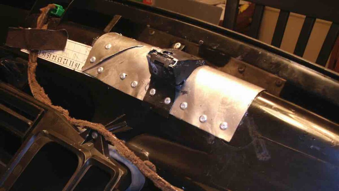
From here I began the new mounting bases. I started on the mounts that were still in relatively good shape so as to come up with methods and procedures that I could use on the mounts that were going to be patched together. I roughly formed a full 5”x 7” piece of the aluminum flashing around the contour of the defroster duct and then “eyeballed” a spot to cut out the rectangular piece to slide around the existing dash mount. Once again, the Dremel tool with the cutoff wheel is handy to cut the rectangular opening in the middle of the sheet. Most of the sheets needed a relief cut to allow the aluminum to take the shape of the molded air duct.
With the opening cut, I finished forming the aluminum around the duct and then drilled holes to accept pop rivets. The rivets were standard 1/8” diameter, 1/4” grip aluminum rivets. When drilling the holes, push a rivet into the hole you just drilled before drilling the next hole. This keeps the plate form shifting as you drill the holes. For the rivets on the “nose” of the duct you need to spot the holes high enough and at an angle that will allow the rivet tool to clear the front portion of the dashboard. I then removed the new backer plate, cleaned and deburred the inside surface, and wiped down the duct itself where the back plate would fit. On most of the new backer plates I had to make a relief cut so as to allow the plate to follow the original duct contour.
What I wanted to accomplish was effectively a laminate for the backer plate. At this point I mixed up about 1/3 of the tube of epoxy and spread it evenly across the backer plate. And then repositioned it on the duct. I then started the rivets again, starting in the corners and worked my way back. Have your drill with an 1/8” bit hand at this step as you may need to re-drill some of the holes. The epoxy starts to go off in about 4 ½ minutes so time is of the essence. You want to get the backer plate in place and riveted down while the epoxy is still fluid. The tighter the aluminum plate fits to the contour of the duct the better the overall lamination will be. Once the backer is riveted down you can mix up a bit more epoxy and then rivet the new mounts in position.
Having completed the mounts that were still in one piece I moved on to the more daunting task of trying to rebuild the other old mounts that had completely detached from the duct. Find what pieces you can and, start by epoxying the pieces in place. The main mount will usually have at least a portion where it can be matched up to spot its original location and orientation. Keep in mind that this part of the repair will not be structurally significant, it simply provides a location and orientation of the original mount to locate and orient the new mounting bracket that will do all of the work. Also at this stage I cut appropriately sized patches to cover the remaining gaps in the ductwork where the pieces were too small to try to glue back in place.
For these parts you appreciate how quickly the epoxy will set up, about the only way to piece the parts back together is to hold the mount in place with your fingers until the epoxy sets. Once the pieces are set in place you can continue with the backer plate fabrication and the installation of the new mounts.
Another area of decay on my dashboard was the foam covered tape that holds the wiring harnesses together. They had basically turned into a sticky goo and they no longer effectively held the harness in place. I purchased a variety of pieces of split loom and spiral loom and cleaned up the wiring harnesses while the dash was out.
Here are some pictures of the dash as it progressed toward completion for re-installation.
The foam gasket around the climate unit and the dash had also seriously deteriorated so I picked up a roll of 3/8” wide by 3/16” thick foam weatherstripping at the hardware store. Here I just cut the pieces and stuck them in place side by side to more or less replicate the original shape of the OEM foam gasket.
To my delight all of the mounting screws started with no real difficulty. It is, of course, important to start all four of the mounts before torquing them down. As far as torque itself goes I tightened the bolts to “snug” plus about an extra ½ turn. I could tighten them more but at this stage I want things to set and adapt. If I need to tighten them further I can easily do so by simply removing the cowl cover.
At this stage, with only a few miles on roads that are decent, the dash is silent and the lower dash panels and glove box door fit in place as they should.
As a bonus, the A/C system held a -25 PSI vacuum perfectly for over 48 hours. After recharging with R-134A, the air is ice cold.
There may be and I hope for revisions as this thread progresses but there will be no version 3.0. If this all falls apart again I plan to douse the car with gasoline and put a match to it. It makes me sick that such a mechanically excellent car suffers from such poor plastic and adhesive material choices.
…Lee
Dashboard Mount Repair – Version 2.0
Last Updated on March 21, 2022